


Power Management IC Basics Vol. 7:
What Is a DC/DC Converter? Part 3
Introduction
Hello, everyone. This is "S" again. In the previous volume, I mentioned that the energy stored in and released from an inductor, which is an element of the buck DC/DC converters, is used for the operation of the buck DC/DC converters. This time, I will explain that the function of energy stored in and released from the inductor realizes the boost operation which makes higher output voltage than input voltage and the inverting operation which makes negative output voltage from the positive input voltage by just changing how the power supply, an inductor, and a switch are connected. I will also explain control methods other than time ratio control.
Voltage Generation by Cutting Off the Inductor Current
An easy circuit for explanation is shown in Figure 1. Consider the case that a constant current, I = Vin / R, flows through the inductor, and the inductor voltage between point A and point B is Vin as the initial state. In this situation, if SW2, between the inductor and resistor R, turns off, how the voltage of point B changes? Even if the SW2 turns off, the inductor tries to flow the current (I = Vin / R) continuously, the voltage of point B rises drastically, and a kind of surge voltage is generated with positive direction. Boost DC/DC converters control this operation to generate a stable voltage higher than the input voltage. On the other hand, from the initial state, if SW1, between the inductor and power supply Vin, turns off, how the voltage of point A changes? Even if SW1 turns off, the inductor tries to flow the current (I = Vin / R) continuously, the voltage of point A goes down drastically, and a kind of surge voltage is generated with negative voltage less than 0V. Inverting DC/DC converters control this operation to generate a stable voltage lower than 0V.
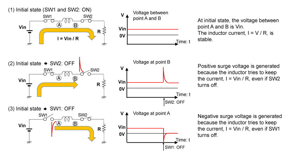
Figure 1. Surge Voltage by Inductor Current Interruption
Boost DC/DC Converters
In terms of boost DC/DC converters, Input power supply: Vin, Inductor L, SW1, SW2, Output capacitor Cout are connected as shown in Figure 2. According to Figure 2, the operation can be explained as follows:
- Step1: When SW1 turns on, the current from the power supply Vin flows through the inductor to the GND and gradually increases, and energy is stored in the inductor.
- Step2: When the SW1 turns off and SW2 turns on, the inductor current continues to flow. During this Step2, the energy stored in the inductor is released.
With this current the output capacitor is charged with this current, and the output voltage rises. I hope you can imagine that the output voltage, Vout, rises by repeating Step1 and Step2.
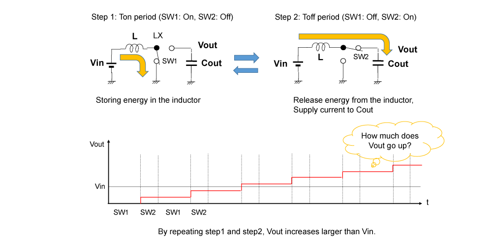
Figure 2. Operation Principle of Boost DC/DC Converters
Then, by how much does the output voltage go up? The answer is shown in Figure 3.
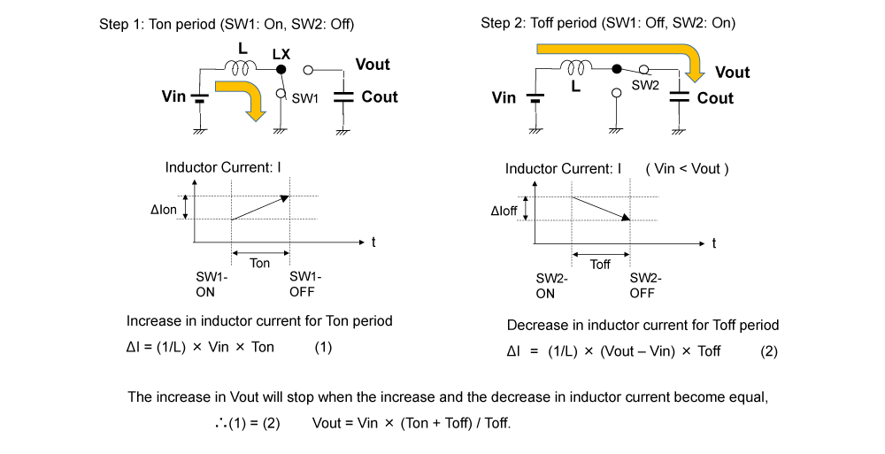
Figure 3. Operation Analysis of Boost DC/DC Converters
If voltage "V" is forced across an inductor with inductance "L" for the time period "T", then the amount in inductor current, ΔI, can be described by the formula below:
ΔI = (1 / L) × V × T
Step1: SW1 turns on for Ton period. The input voltage Vin is forced across the inductor for Ton period. The increase in inductor current ΔIon can be calculated as shown in the next formula:
ΔIon = (1 / L) × Vin × Ton. ... (1)
Step2: SW2 turns on for Toff period. The voltage "Vout - Vin" is forced across the inductor for Toff period. The decrease in inductor current ΔIoff can be calculated as shown in the next formula:
ΔIoff = (1 / L) × (Vout – Vin)× Toff. ... (2)
When the increase in inductor current, ΔIon, and the decrease in inductor current, ΔIoff, are equal, the increase in output voltage stops. Thus, by using equation (1) = (2), and we obtain Vout as:
Vout = Vin × (Ton + Toff) / Toff.
As described above, the configuration is shown in Figure 2, and the voltage higher than Vin is generated by switching two switches at a certain time ratio. The output voltage is adjusted by the time ratio. I hope you now understand the operation of boost DC/DC converters.
Output Voltage Smoothing by Capacitor
Buck DC/DC converters supply a current to the output load during both Ton and Toff periods. However, boost and inverting DC/DC converters do not supply a current to the output load during the Ton period.
In buck DC/DC converters, the filter is composed of an inductor and a capacitor, and the inductor also plays a "smoothing" role. However, in boost DC/DC converters, the inductor does not contribute to smoothing, and only the capacitor plays the role of smoothing. Therefore, the capacitor with a relatively large capacitance is required. The role of the inductor in boost DC/DC converters is only "energy store and release."
Output Current of DC/DC Converters
Suppose that the average current from Vin is Iin, and the output current is Iout, then,
Vin × Iin = Vout × Iout
By this equation, the bigger the ratio of the output voltage against the input voltage, or boost ratio is, the lesser the maximum output current is.
* While Vin × Iin is supplied during the Ton period and the Toff period, current flows through the inductor to GND during the Ton period. Therefore, one might think that energy is consumed by the current consumed during this period, but energy is not consumed during the Ton period. This is the period during which energy equivalent to Vin × Iin is stored in the inductor.
Inverting DC/DC Converters
To compose an inverting DC/DC converter, input power supply: Vin, inductor: L, SW1, SW2, output capacitor: Cout are connected as shown in Figure 4. Based on Figure 4, the operation can be explained as follows:
- Step1: When SW1 turns on, the current from the power supply Vin flows through the inductor to the GND and gradually increases. At this time, energy is stored in the inductor by the current flowing through the inductor.
- Step2: When the SW1 turns off and SW2 turns on, the inductor current continues to flow. During this Step2, the stored energy in the inductor is released as a current.
The output capacitor is discharged with this current, and the output voltage decreases. You can imagine that the output voltage, Vout, decreases below 0 V by alternately switching between Step 1 and Step 2.
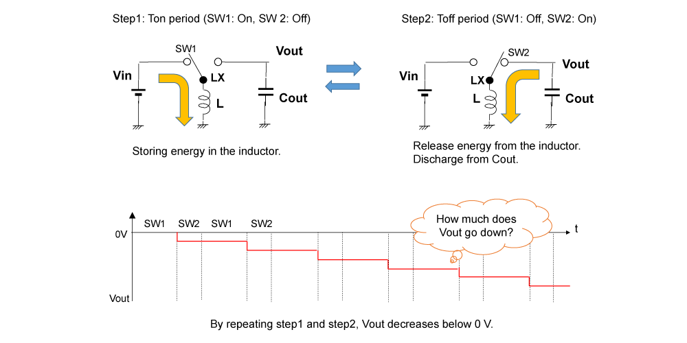
Figure 4. Operation Principle of Inverting DC/DC Converters
Then, how much does the output voltage go down? The answer is shown in Figure 5.
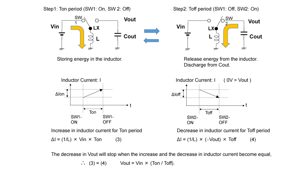
Figure 5. Operation Analysis of Inverting DC/DC Converters
It is analyzed in the same way as boost DC/DC converters.
Step1: SW1 turns on for Ton period. The input voltage Vin is forced across the inductor for Ton period. The increase in inductor current ΔIon can be calculated as shown in the next formula:
ΔIon = (1 / L) × Vin × Ton. ... (3)
Step2: SW2 turns on for Toff period. The voltage "|Vout|" is forced across the inductor for Toff period. The decrease in inductor current ΔIoff can be calculated as shown in the next formula:
ΔIoff = (1 / L) × |Vout| × Toff. ... (4)
When the increase in inductor current, ΔIon, and the decrease in that, ΔIoff, are equal, falling of the output voltage stops. Thus, by using equation (3) = (4), and we obtain Vout as:
|Vout| = Vin × (Ton / Toff).
As described above, the configuration is shown in Figure 4, and the voltage below 0V is regulated by switching two switches at a certain time ratio. The output voltage is adjusted by the time ratio. I hope you now understand the operation of inverting DC/DC converters.
Image of Output Voltage Generation of Buck/Boost/Inverting DC/DC Converters
For each topology of DC/DC converters, when the increasing inductor current amount, ΔIon, and decreasing inductor current amount, ΔIoff are equal, suppose that the voltage between both edges of the inductor is Von during Ton, Voff during Toff, then the next formula is true.
Von × Ton = Voff × Toff
As shown in Figure 6, the image of the output voltage of the DC/DC converters can be easily described.
Buck DC/DC Converters
Vout during Toff period is filled and averaged by (Vin − Vout) × Ton,
∴ Vout = Vin × Ton / (Ton + Toff).
Boost DC/DC Converters
Vin × Ton / Toff is added to Vin,
∴ Vout = Vin × (Ton + Toff) / Toff.
Inverting DC/DC Converters
Negative voltage of Vin × Ton / Toff is generated,
∴ Vout = -Vin × Ton / Toff.
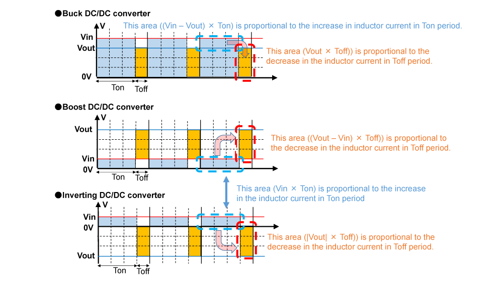
Figure 6. Image of Output Voltage Generation of Buck / Boost / Inverting DC/DC Converters
DC/DC Converters' Control Method
PWM Control
The control method that regulates a constant voltage by controlling the time ratio as explained so far is called PWM control. PWM stands for pulse width modulation. In PWM control, the switching frequency is constant, and Ton time period (On duty) is controlled. The control circuit is monitoring the output voltage, and by adjustment of the on duty ratio, the output voltage is regulated.
Continuous Conduction Mode
So far, based on the condition that the increasing and decreasing amount of the inductor current is same, the calculation of the output voltage is explained. This condition means that the inductor current should be continuous. Therefore, the relation between the output voltage and the time ratio which determines the output voltage described above assumes that the inductor current is continuous. This mode in which the inductor current is continuous is called the continuous conduction mode. Continuous conduction mode is true with the relation of the load current, Iout, and the increase/decrease range of the inductor current (ripple current), ΔI, is described as shown in the next formula:
Iout ≥ 1/2 × ΔI.
Here, especially, when Iout = 1/2 × ΔI is true, this is called critical mode.
Refer to Figure 7.
Discontinuous Conduction Mode
When the relation between the load current, Iout, and the increase/decrease range of the inductor current (ripple current), ΔI, is shown below, in the forced PWM mode,
Iout < 1/2 × ΔI,
the inductor current flows in reverse.
The reverse current from the inductor is a factor in efficiency loss, therefore, SW turns off to prevent the reverse current. If Iout < 1/2 × ΔI is true, then the inductor current is discontinuous in that case.
As shown in Figure 7, in PWM control of current discontinuous conduction mode, the output voltage is regulated by controlling Ton period depending on the load current. In PWM control, regardless of the load current, the frequency is constant, therefore, in the case of light load where the load current is low, the power consumed by DC/DC converters is not negligible compared to the power consumed by the load, resulting in a lower efficiency.
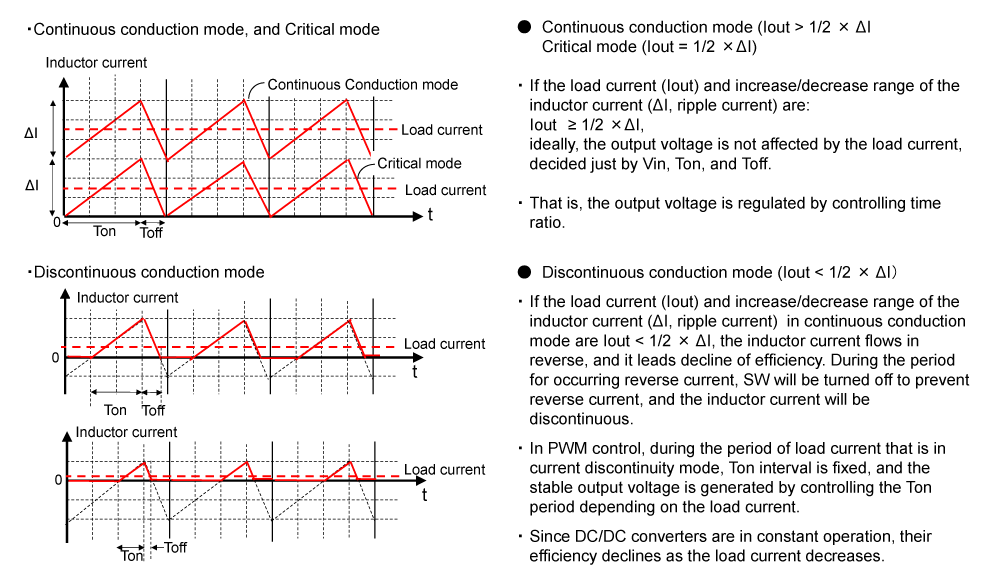
Figure 7. Continuous Conduction Mode and Discontinuous Conduction Mode in PWM Control
VFM/PFM Control
To improve the efficiency at light load, other control method, VFM (Variable Frequency Modulation)/PFM (Pulse Frequency Modulation) control is used. As for this control method, the output voltage is monitored, and if the output voltage becomes less than the set output threshold, switching operation starts to provide output current to the load. On time, pulse (Ton period), of the switching is constant, and the number of times switching occurs changes depending on the load current. If the load current is small, the interval of the pulse is long, on the contrary, if the load current is large, the interval of the pulse will be short. Since switching is only performed when a voltage drop is detected, high efficiency can be achieved at light load.
Refer to Figure 8.
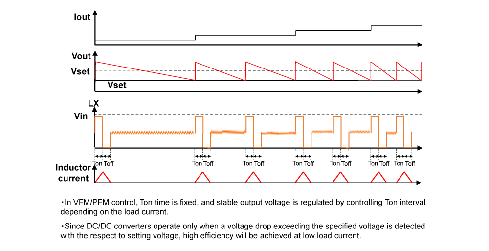
Figure 8. VFM/PFM Control Operation Waveform Image
In the table on the left side of Figure 9, the comparison between PWM control and VFM/PFM control is shown. The mainstream of DC/DC converters is to use PWM control for stable operation at heavy load current and to switch to VFM/PFM control for efficiency at light load.
Comparison between PWM Control and VFM/PFM Control
Efficiency:
In PWM control, regardless of the load current, switching frequency is constant, therefore, the efficiency at light load is worse than VFM/PFM control. In VFM/PFM control, the switching operation starts only when the output voltage becomes less than the specified level, therefore efficiency at light load is much better than PWM control method. Refer to the graph on the right in Figure 9; the efficiency vs. output current of PWM control and VFM/PFM control is shown in the graph.
Consumption Current:
(Although overlapping with "Efficiency") PWM control operates at a constant switching frequency regardless of the load current, therefore, the current consumption is almost constant. On the other hand, VFM/PFM control changes the switching frequency depending on the load current, therefore, the current consumption can be reduced at light load especially.
Ripple Voltage:
When compared to discontinuous conduction mode, PWM control provides current during Ton period depending on the load current, therefore, the output ripple voltage is suppressed to a small level. VFM/PFM control aims to improve efficiency by increasing the switching interval with a constant Ton period, and the Ton period is set relatively long, therefore, the output ripple voltage is large.
Transient Response:
In PWM control type, Ton time varies depending on the load current variation. Therefore, the transient response of PWM control is better than that of VFM/PFM control which has fixed Ton time.
Noise:
Because DC/DC converters regulate the output voltage by switching operation, switching noise is generated. The switching noise caused by PWM control is determined by switching frequency, therefore, it is easy to design filters to take a countermeasure. But in VFM/PFM control, the switching frequency varies depending on the load current, therefore, taking a countermeasure may be difficult.
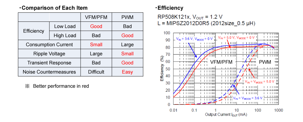
Figure 9. Comparison between PWM Control and VFM/PFM Control
Conclusion
I explained that by connecting the power source, inductor, and switches in different ways, and by storing energy in the inductor or release from the inductor, boost DC/DC converters which make higher voltage than input voltage, or inverting DC/DC converters which make negative voltage can be implemented. I also explained the features of PWM control and VFM/PFM control as control methods.
In the next volume, I will explain other control methods of DC/DC converters.
Thank you for reading.
Power Management IC Basics
- Vol. 1
What Are Power Management ICs? - Vol. 2
What Is a Linear Regulator (LDO Regulator)? Part 1 - Vol. 3
What Is a Linear Regulator (LDO Regulator)? Part 2 - Vol. 4
What Is a Linear Regulator (LDO Regulator)? Part 3 - Vol. 5
What Is a DC/DC Converter? Part 1 - Vol. 6
What Is a DC/DC Converter? Part 2 - Vol. 7
What Is a DC/DC Converter? Part 3 - Vol. 8
What Is a DC/DC Converter? Part 4 - Vol. 9
What Is a DC/DC Converter? Part 5 NEW
Author profile

Lecturer S (Nisshinbo Micro Devices Inc.)
For a long time since he joined the company, he has been involved in various analog and digital designs such as gate arrays, microcomputers, memories, and power management ICs. After that, he also mastered the test technology of compound power supply ICs and became a specialist in design, testing and education on his specialty. His easy-to-understand explanations and polite guidance from the listener's perspective are well received by new engineers who join our company every year. His achievements are highly commended, and now he is working as a senior engineer in training younger generations and as a consultant for new technologies.
FAQ: DC/DC Switching Regulators
- What is a soft-start function?
- What is the circuit configuration and pin treatment when not using the R1283 boost circuit?
- The data sheet for the FB pin of the NJM2369 says that the source current is 40 to 200µA, but does this pin have a built-in pull-up resistor?
- What is an over-current protection (OCP) for DC/DC converters?
- What is externally programmable maximum duty cycle?