


Power Management IC Basics Vol. 1:
What Are Power Management ICs?
Introduction
Hello, everyone. I am S at Nisshinbo Micro Devices Inc. I will write a series of contents titled “Power Management IC Basics” from now. I hope you enjoy it!
Do you know a lot of Power Management ICs are used in every part of our daily lives? They supply appropriate voltages that are necessary for electrical appliances to operate or function properly. In other words, they are essential parts for electrical equipment.
We are going to talk about power management ICs: the types and roles, and how those ICs contribute to our lives.
Now let’s get started.
What Are Power Management ICs?
It is common knowledge that electricity comes from the wall outlet in your home. In the US, many electrical appliances utilize a 120 V alternating current (AC)*1 as their power source with an AC power cord connected to an outlet. However, not all the components inside home appliances can utilize the alternating power as its power source*2. The 120 V AC must first be converted to direct current (DC), and the DC is supplied to electronic circuits. Electrical appliances are equipped with various electronic circuits necessary for electronic control, and each of them has its own electrical requirements. Power management ICs function to supply stable source voltages to the circuits according to each requirement.
As shown in Fig. 1, power management ICs are used not only in domestic appliances but also in every electrical product.
- *1Voltage strength of alternating current differs from country to country, but the basic principle of utilizing AC is the same.
- *2Conventional filament lamps, fluorescent lights, electrical heaters, dryers, etc. utilize the AC power without conversion.
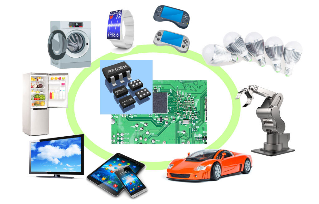
Figure 1. Products Using Power Management ICs
How Are Power Management ICs Used?
How are power management ICs selected and combined to find the correct source voltages required of each device*3? We will explain the selection of power management ICs with a power tree of a laptop PC for an example.
Laptop PCs can be constructed with various components, according to PC’s specifications, performance, cost, etc. In addition, each device requires different source voltages, power supply, efficiency, noise, etc. Therefore, the choice and combination of power management ICs also vary.
Fig. 2 shows an example of the power tree to supply electricity to the main devices inside a laptop PC.
- *3Here, the word "device" means a general term for electronic components such as ICs, LEDs, etc.
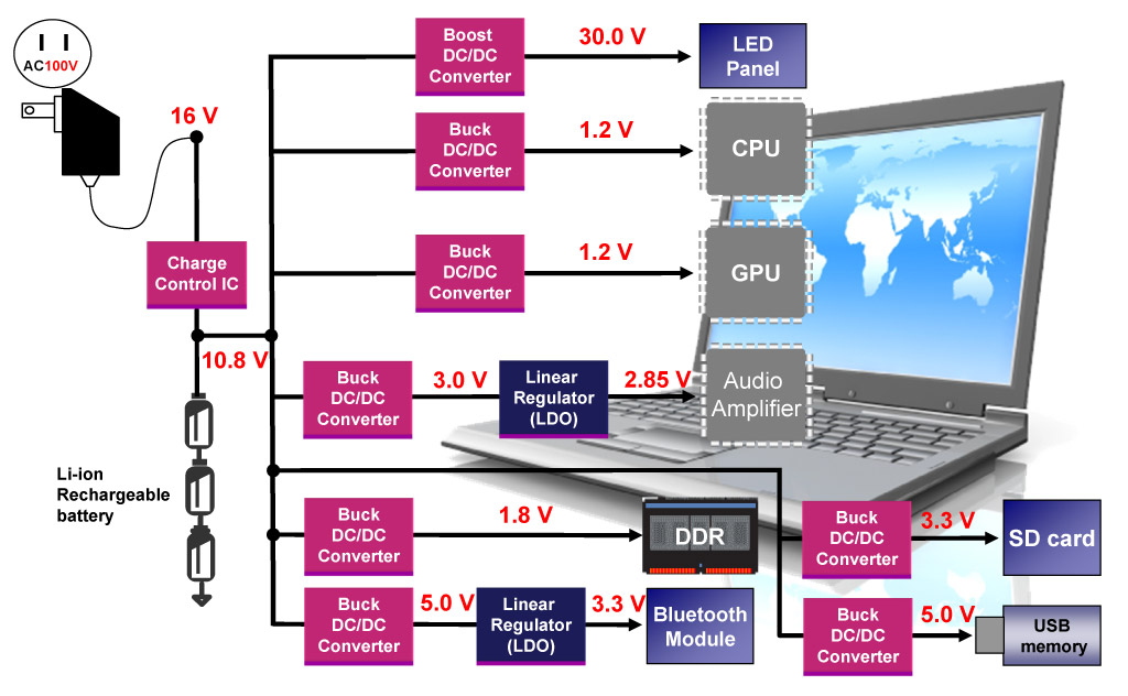
Figure 2. Power Tree Example of Laptop PC
The laptop PC operates by acquiring electric power from the AC adapter and the Li-ion secondary battery. The AC adapter converts the 120 V AC into a 16 V DC and supplies the converted voltage to the PC while at the same time, the charge control IC charges the Li-ion battery. When the AC adapter is disconnected, the Li-ion battery supplies electricity to the whole power tree of the system.
The CPU and GPU circuits are densely packed and manufactured using the latest microfabrication technologies. These technologies consume large current and require very low voltage. Therefore, buck (step-down) DC/DC converters*4 are commonly adopted for use in the source lines to the CPU and GPU to achieve efficient conversion. However, DC/DC converters are inappropriate for audio amplifiers because the switching noise generated by those converters deteriorates sound quality. Therefore, a 2.85 V linear regulator (LDO*5) is often inserted between a DC/DC converter and an audio amplifier to reduce the switching noise and improve sound quality.
In a back-light LED panel, LEDs are connected in tandem. It requires more than 16 V to operate. Therefore, a step-up converter supplies a 30V to the back-light LED panel*6.
As is shown above, devices inside the laptop PC have different operating voltages and electrical characteristics*7 from each other. Therefore, power management ICs are necessary for electrical products.
- *4Two control methods are utilized in regulators: linear method and switching method. Regulators using linear method are called linear regulators, and those with switching method are called switching regulators (or simply converters).
- *5LDO regulators are a kind of linear regulators that operate properly despite the small difference between input and output voltages.
- *6When using LDO regulators, the output voltage is inevitably lower than the input voltage. On the other hand, DC/DC converters can do both buck (lower) and boost (raise) the input voltage. Buck (step-down) DC/DC converters generate the output voltages lower than the input, and boost (step-up) converters generate the output voltages higher than the input.
- *7The word "electrical characteristics" refers to specifications of power management ICs such as the amount of power supply, efficiency, noise, etc.
Power Management IC Classification by Function and Application
Power management ICs include many ICs that play various roles in addition to those mentioned above. (Ex. voltage detectors, supervisory, etc.)
Figure 3 shows the classification of power management ICs by their functions and applications.
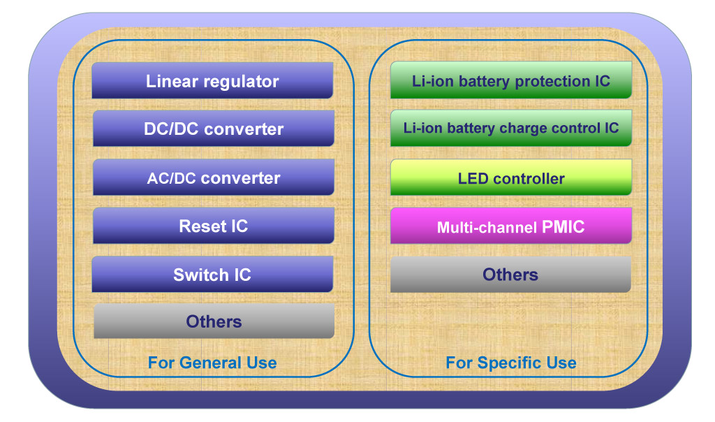
Figure 3. Classification of Power Management ICs
The left box of the figure lists single-function ICs for general purpose. Those ICs are used in a wide variety of electrical equipment to control electricity. Linear regulators, DC/DC converters, AC/DC converters, reset ICs, switch ICs, etc. are included in this category.
Power management ICs in the right side are designed for specific purposes. These ICs are optimized for specific equipment with strict electrical requirements. Li-ion battery protection ICs, Li-ion battery charge control ICs, LED controllers, power management units (PMU) that integrate multiple functions in a single package are included.
Roles of Power Management ICs
We will explain to you the roles of three types of power management ICs: 1) regulators, 2) reset ICs, and 3) switch ICs. All of these contribute to efficient and stable operation of electrical products and building today’s economical society.
1. Regulators
Regulators supply stable source voltage and power according to requirements of each device. Linear regulators, DC/DC converters, etc. are included in this type.
For example, a Li-ion battery adopted in mobile phones or smartphones supplies about 4.2 V when fully charged. However, the processor inside the phones requires only about 1.2 V to operate properly. Voltage exceeding this voltage requirement can cause permanent damage to the processor. Over a period of time and with every battery charge cycle, the output voltage of the battery starts to diminish. In short, some devices are necessary to continue converting the battery voltage into a stable and reliable source for the processor, even though the battery voltage may gradually decrease.
Regulators maintain a stable output voltage regardless of input fluctuation. As long as the battery voltage satisfies their operating requirements, regulators will continue to supply a stable 1.2 V to the processor.
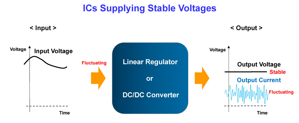
Figure 4. Operation of Regulators
2. Voltage Detectors (Reset ICs)
As mentioned above, each device has a different operating supply voltage range. When the supply voltage is outside the device input range, the device will operate improperly. When this happens the device must be stopped. Even after the supply voltage returns to the preset value, the device will not return to its normal state.
The same thing will happen at system startup because the internal state is unstable when voltages are supplied and it must be reset. To achieve this, every device has a reset pin to stop operating and initialize the internal state to the preset condition. Internal initialization enables the devices to start proper operation.
Voltage supervisor ICs monitor whether the supply voltage is within the voltage detector threshold range and will output a reset signal when the supply voltage is out of the voltage range. When a reset signal is sent to a device through its reset pin, the device stops operating and its internal state can be reset. Voltage supervisor ICs are mainly used to reset load devices, so they are usually called reset ICs.
Figure 5 shows the operation of reset ICs. If the input voltage (monitored voltage) is lower than the preset voltage threshold (voltage detector threshold), the reset signal will output 0 V, and this 0 V signal means a reset signal for each device.
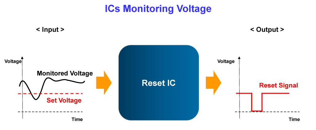
Figure 5. Operation of Reset ICs
3. Switch ICs
Switch ICs are ICs which are inserted in the power line and turn the power supply on / off. If multiple devices are connected to a power line of the same voltage, inserting a switch IC makes it possible to turn power supply on / off according to the state of each device, which reduces the power consumption of the whole system. Switch ICs used in this way are called load switch ICs.
Of course, simple MOSFETs can play a role as a switch. However, when they are turned on, MOSFETs cannot prevent large current from momentarily flowing from input to the output circuits. The large current is called inrush current. Inrush current causes problems such as transient drop of input voltage, etc. To prevent this from happening, switch ICs can include protection circuits such as a soft-start to prevent a transient drop of input voltage, an auto-discharge to discharge the output charge as soon as the power line is turned off, and so on. Although it is possible to provide the same supply voltage by using a linear regulator or DC/DC converter, it is more beneficial to use switch ICs when it comes to reducing supply current and the number of external components.
Figure 6 shows the operation of switch ICs. As the control signal turns from high to low, the power supply to the output load stops, and at the same time the output voltage is quickly turned to 0 V by the auto-discharge. When the control signal turns from low to high soon after the power supply starts, the input voltage drop is prevented thanks to the soft-start that gradually increases the output voltage.
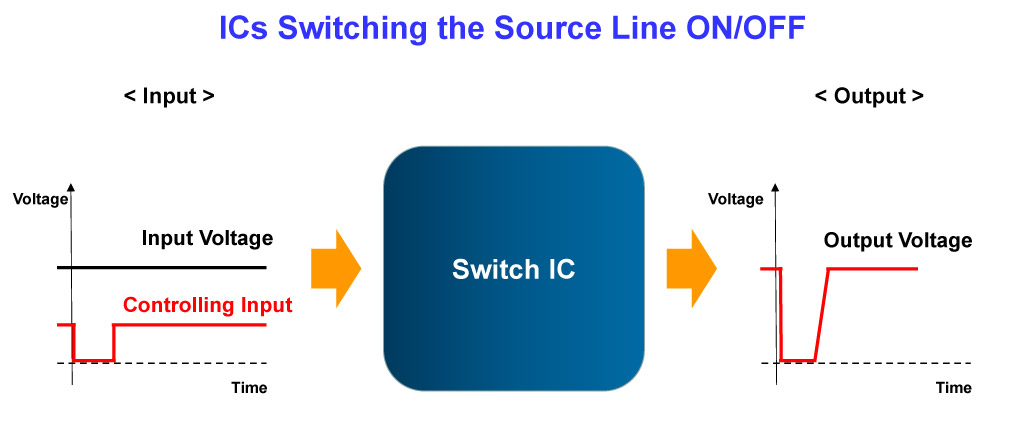
Figure 6. Operation of Switch ICs
Conclusion
Power lines are seldom drawn on logic circuits or analog circuits using operational amplifiers. It is common knowledge for everyone who uses an electrical appliance that electricity is required to power the system. However, what is commonly overlooked is the importance of the electric source and system power requirement. The circuit designer must consider the source of electricity and specific power requirement of each electrical device to design a stable and reliable system. Processors like Dual Core or Quad Core in smartphones connect to many components and would never work without power management ICs. Power management ICs are the “Unsung Heroes”―they are essential components that support safe and proper operations of electronic systems behind the scenes.
Power Management IC Basics
- Vol. 1
What Are Power Management ICs? - Vol. 2
What Is a Linear Regulator (LDO Regulator)? Part 1 - Vol. 3
What Is a Linear Regulator (LDO Regulator)? Part 2 - Vol. 4
What Is a Linear Regulator (LDO Regulator)? Part 3 - Vol. 5
What Is a DC/DC Converter? Part 1 - Vol. 6
What Is a DC/DC Converter? Part 2 - Vol. 7
What Is a DC/DC Converter? Part 3 - Vol. 8
What Is a DC/DC Converter? Part 4 - Vol. 9
What Is a DC/DC Converter? Part 5 NEW
Author profile

Lecturer S (Nisshinbo Micro Devices Inc.)
For a long time since he joined the company, he has been involved in various analog and digital designs such as gate arrays, microcomputers, memories, and power management ICs. After that, he also mastered the test technology of compound power supply ICs and became a specialist in design, testing and education on his specialty. His easy-to-understand explanations and polite guidance from the listener's perspective are well received by new engineers who join our company every year. His achievements are highly commended, and now he is working as a senior engineer in training younger generations and as a consultant for new technologies.