


Power Management IC Basics Vol. 6:
What Is a DC/DC Converter? Part 2
Introduction
Hello everyone, this is "S" again. In previous time, I explained that buck DC/DC converters generate a stable voltage by time ratio control to make you understand easily about DC/DC converters (switching regulators *). This time, I will talk about "100% efficiency is ideally possible to be realized by control switching time ratio." Then I will explain the function of inductors (coils) that achieve the content described above. Finally, I will compare features of DC/DC converters with those of linear regulators and explain what kind of applications they are used for based on their features.
* The term switching regulator will be omitted hereafter.
Time Ratio Control and Efficiency of Buck DC/DC Converters
Let me review the lesson from last time. Figures 1 and 2 shows voltage generation method of buck DC/DC converters, which are the same figure in the previous time. I explained that pulse output from the time ratio-controlled DC/DC converters is converted to a constant voltage corresponding to the time ratio by the LC low-pass filter.
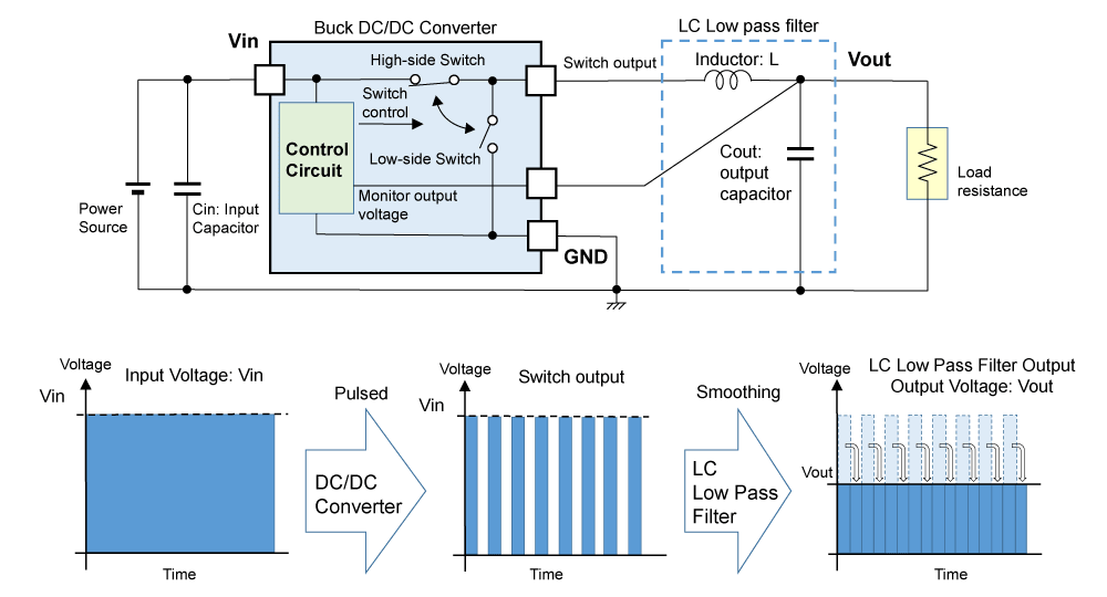
Figure 1. Voltage Generation of Buck DC/DC Converters (1)
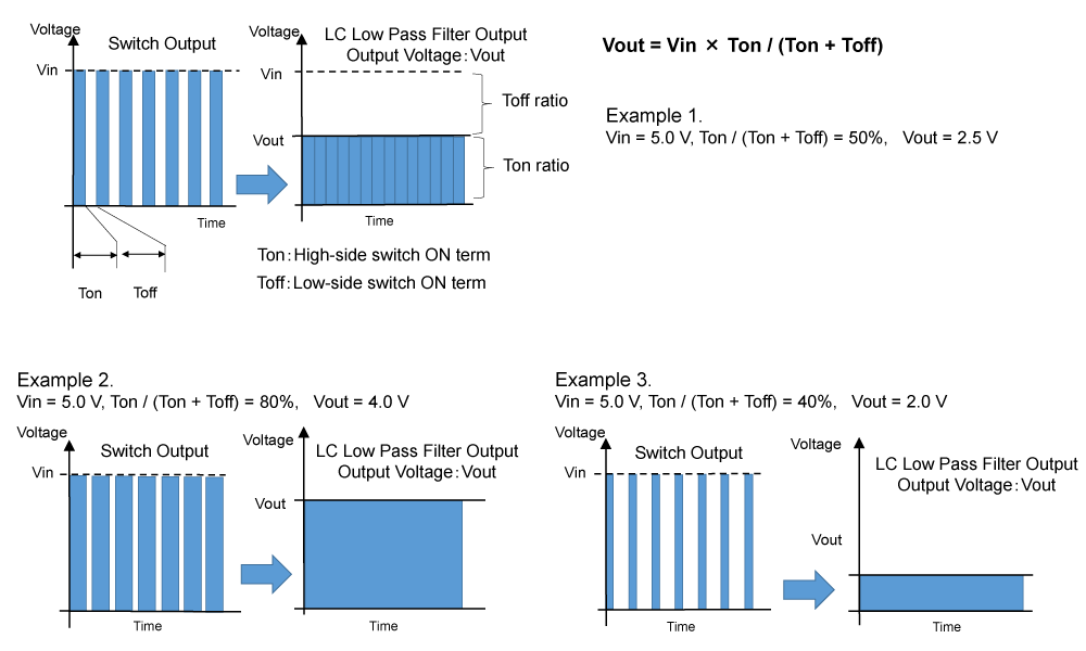
Figure 2. Voltage Generation of Buck DC/DC Converters (2)
What can we find out if we focus on power supply side?
Input voltage and input current are converted to pulse train by DC/DC converters. Power is supplied only during Ton period, and no power is supplied during Toff period.
How does DC/DC converters regulate output voltage during Toff time? Inductor is the answer for that. As I explained, inductor smooths out time-division pulses and can be a filter to generate stable output with output capacitor. In addition, the inductor has an important role of storing and releasing energy.
The Characteristics of an Inductor and its Function in DC/DC Converters
When a current flows through an inductor, energy determined by the current and inductance value of the inductor is stored in the inductor as magnetic energy. A capacitor also stores electric energy by charging and keeps energy until it releases, but an inductor releases energy as soon as the power supply is stopped.
Figure 3 shows the operation of switches and the current flow of DC/DC converters in each switching state. Step 1 is Ton period, and Step 2 is Toff period. During Ton period, power source supplies required current by load, Iout, through the inductor, and the inductor stores energy by that current of Iout. On the other hand, during Toff period, energy stored in the inductor is released and the current is supplied from GND. By this operation, current is supplied from power source only during Ton period, but the load keeps receiving current.
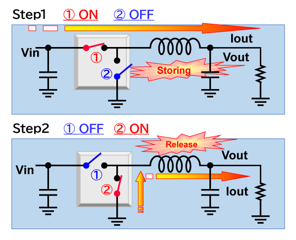
Figure 3. Operation of DC/DC Converters
Suppose that a 100 mA load is necessary, 100 mA is supplied from power source during Ton period and 100 mA is supplied from GND during Toff period.
Input power, Vin × Iout is supplied during Ton / (Ton + Toff) period. Thus,
Input power = (Vin × Iout) × (Ton / (Ton + Toff)). ... (1)
On the other hand,
Output power = Vout × Iout. ... (2)
As I explained in the lesson last time,
Vout = Vin × (Ton / (Ton + Toff)). ... (3)
Substituting equation (3) in (2),
Output power = Vin × (Ton / (Ton + Toff)) × Iout. ... (4)
The Input power of (1) and the output power of (4) are equal.
As I explained in the volume #4,
Efficiency (%) = Output power(W) / Input power(W). ... (5)
You can say that ideal efficiency of DC/DC converters is 100%.
This is the greatest merit of DC/DC converters.
You may find comparison between linear regulators and DC/DC converters in Figure 4.
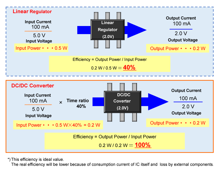
Figure 4. Comparison of Efficiency between Linear Regulators and DC/DC Converters
Example) Consider the case that Vin = 5 V, Vout = 2 V, and Iout = 100 mA.
Linear regulators generate stable output voltage by consuming power with internal output driver transistor. As described in the volume #4, ideal efficiency of linear regulators is calculated as below.
Efficiency (%) = Output voltage(V) / Input voltage(V).
Therefore, in the case that Vin = 5 V, Vout = 2 V, and Iout = 100 mA, the efficiency will be 40%.
On the other hand, for buck DC/DC converters, this case corresponds to the Example 3 in Figure 2, where time ratio of Ton / (Ton + Toff) is 40%.
For output power, Vout × Iout = 2 V × 100 mA = 200 mW,
only 40% of input power (5 V × 100 mA) is needed.
Input power is Vin × Iout × time ratio = 5 V × 100 mA × 40% = 200 mW.
Output power is same as input power, and efficiency will be 100%.
Therefore, ideal efficiency of buck DC/DC converters will be 100%.
*Note that Figure 4 and the explanations above assume the ideal case that consumption current of linear regulators and DC/DC converters or loss by external components are not considered.
Comparison of Linear Regulators and DC/DC Converters
Now let's compare linear regulators and DC/DC converters and think about their use.
Linear regulators vs DC/DC converters
| Linear regulators | DC/DC converters | Remark | |
|---|---|---|---|
| Efficiency | Bad | Good |
|
| Output current | Small | Large |
|
| Noise | Small | Large |
|
| Output topology | Step-down only | Step-up, Step-down, Step-up and down, and Inverting |
|
| Circuit complexity | Small | Large |
|
Example of application
- Low noise power supply → LDO
- Large current, high efficiency → DC/DC converters
Efficiency
As I explained above, a DC/DC converter ideally achieves 100% efficiency; this is the greatest advantage of a DC/DC converter. Actual efficiency will be 80 to 95% by the loss of a DC/DC converter itself and switching loss and others.
On the other hand, a linear regulator cannot achieve such high efficiency as a DC/DC converter because a linear regulator generates required voltage by using an output driver that consumes large amount of power, and as described above efficiency can be expressed as:
Efficiency (%) = Output Voltage(V) / Input Voltage (V).
High efficiency close to DC/DC converters can be realized by making voltage difference between input and output as small as possible with ultra-low dropout voltage LDO.
Output Current
A DC/DC converter is suitable for large load current devices like CPU since its efficiency is high. On the other hand, a linear regulator is not so suitable for such kind of devices because an output driver consumes large amount of power.
Noise
Linear regulators do not make significant noise basically because they generate output voltage by dividing input voltage with on resistance of their output driver and load resistance.
*Noise here we talk about does NOT mean the white noise or 1/f noise which both linear regulators and DC/DC converters have.
On the other hand, DC/ DC converters switch the input power supply at a time ratio proportional to the output voltage / input voltage, so switching noise is inevitable. This noise generation is a major disadvantage of DC/DC converters. The generated noise frequency is the switching frequency of DC/DC converters and its harmonics. DC/DC converters can be used in applications that are not affected by noise in these frequency bands.
Output Voltage
Linear regulators conduct only step-down operation because they generate output voltage by dividing the input voltage by the on resistance of output driver and the load resistance. On the other hand, DC/DC converters have a major feature that if the energy storage and release functions of the inductor are used, step-up (boost) operation and inverting operation can be realized simply by changing the connection method of the power supply, inductor and switch. (I will explain it in the next lesson.)
Circuit Complexity
The basic internal circuit of a linear regulator consists of only four elements: a reference voltage source, an error amplifier, a feedback resistor, and an output driver transistor, and it is simple. Only an input capacitor and an output capacitor are needed as external components and it is easy to use. On the other hand, DC/DC converters consist of a reference voltage source, an error amplifier, an oscillator circuit and a comparator for controlling the time ratio, a high-side switch, a low-side switch, etc., and the circuit is complicated and large. Note that an inductor is required as an external component; it is difficult to design, and the cost may be high.
Based on the above comparison of features (advantages and disadvantages), the applications of linear regulators and DC/DC converters can be summarized as follows.
Linear regulator
It is suitable for applications that are sensitive to noise such as sensors, and applications that require low current consumption rather than efficiency because load current is small. It may also be used to reduce switching noise of DC/DC converter by inserting it between the load and DC/DC converter to remove the ripple.
DC/DC converter
It is used for applications that require high efficiency, for CPUs and large-scale digital circuits that require a large current on the premise of high efficiency, and for applications that require a higher voltage or negative voltage compared to the input voltage.
Conclusion
This time, I explained that the efficiency, which is the greatest feature of DC/DC converters, can be realized by utilizing the energy storage and release of the inductor, which is a component of DC/DC converters. We also addressed applications of linear regulators and DC/DC converters by comparing them.
Next time, I would like to explain by using the functions of energy storage and release of the inductor, boosting operation that generates higher voltage than input voltage and inverting operation that generates opposite polarity voltage to input voltage simply by changing the connection of the power supply, inductor and switch. I will also talk about the typical time ratio control method.
Thank you for reading through.
Power Management IC Basics
- Vol. 1
What Are Power Management ICs? - Vol. 2
What Is a Linear Regulator (LDO Regulator)? Part 1 - Vol. 3
What Is a Linear Regulator (LDO Regulator)? Part 2 - Vol. 4
What Is a Linear Regulator (LDO Regulator)? Part 3 - Vol. 5
What Is a DC/DC Converter? Part 1 - Vol. 6
What Is a DC/DC Converter? Part 2 - Vol. 7
What Is a DC/DC Converter? Part 3 - Vol. 8
What Is a DC/DC Converter? Part 4 - Vol. 9
What Is a DC/DC Converter? Part 5 NEW
Author profile

Lecturer S (Nisshinbo Micro Devices Inc.)
For a long time since he joined the company, he has been involved in various analog and digital designs such as gate arrays, microcomputers, memories, and power management ICs. After that, he also mastered the test technology of compound power supply ICs and became a specialist in design, testing and education on his specialty. His easy-to-understand explanations and polite guidance from the listener's perspective are well received by new engineers who join our company every year. His achievements are highly commended, and now he is working as a senior engineer in training younger generations and as a consultant for new technologies.
FAQ: DC/DC Switching Regulators
- What is a soft-start function?
- What is the circuit configuration and pin treatment when not using the R1283 boost circuit?
- The data sheet for the FB pin of the NJM2369 says that the source current is 40 to 200µA, but does this pin have a built-in pull-up resistor?
- What is an over-current protection (OCP) for DC/DC converters?
- What is externally programmable maximum duty cycle?