


Thermal Design Support
Increasing integration and miniaturization of electronic components make thermal design critical. Nisshinbo Micro Devices receives many inquiries about thermal resistance from customers. In order to respond to customer's request, Nisshinbo Micro Devices started "Thermal design support" that provides thermal resistance simulation results and thermal resistance data. Please utilize Nisshinbo Micro Devices' thermal design support to analyze thermal characteristics at customer's concept design stage.
Thermal resistance simulation support
- High accuracy thermal resistance data
- Visualization data of heat conduction path in components and boards and heat flux in ambient air
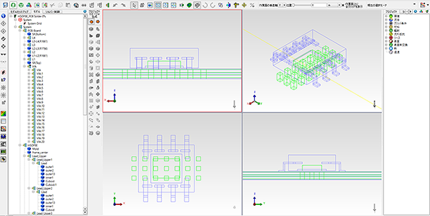
Nisshinbo Micro Devices uses electronics thermal analysis software Simcenter Flotherm (SIEMENS) to create a thermal model. At the design stage of the board, thermal simulation under various conditions such as board size and number of wiring layers can be performed, which can contribute to reduction of design man-hour and development cost. Also, by matching with the structure function measured by the transient temperature measurement system Simcenter T3STER, high accuracy simulation can be done.
Screen of electronics thermal analysis software Simcenter Flotherm
Simulation examples
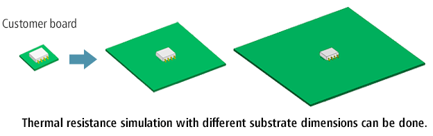
Simulation with different board dimensions
We can simulate thermal resistance by changing the dimensions of the customer's board. Thermal resistance is highly dependent on board dimensions, board structure and so on. The optimal thermal resistance can be studied from simulation.
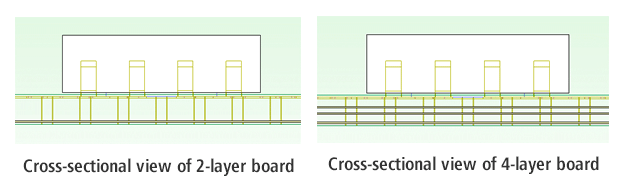
Simulation with different number of wiring layers
Nisshinbo Micro Devices offers thermal resistance of JEDEC-compliant basic 4-layer board, but simulation with different number of wiring layers according to customer's specification is available.
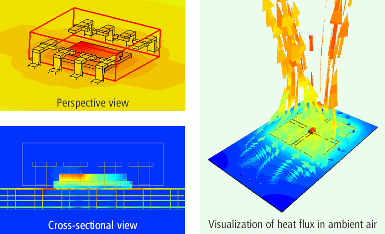
Visualization of heat conduction path and heat flux
We provide data in a visualized form such as a heat transfer path diagram, animation of heat flux in ambient air.
Model creation screen of electronics thermal analysis software Simcenter Flotherm
-
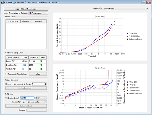
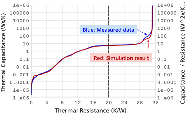
By matching with the structure function measured by the transient temperature measurement system Simcenter T3STER, highly accurate simulation can be performed.
Adjustment between measured data and simulation result
By matching simulation results to measured data, we create high accuracy models.
By using this model, we can improve the accuracy of simulation according to customer's specifications.
-
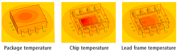
Calculation of thermal resistance
We can calculate the thermal resistance (θja, θjc, ψjt) because the temperature of each part can be known by simulation.
-
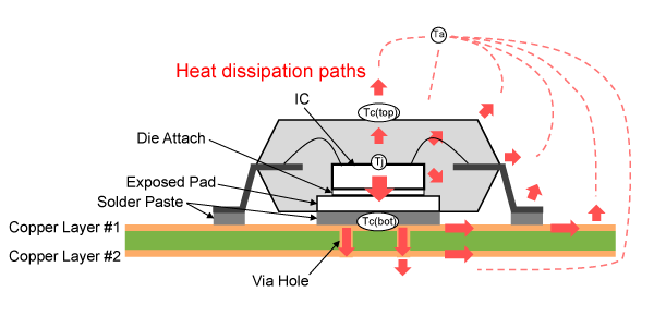
Definition of θja, ψjt and θjc
-
- θja:Thermal resistance between junction temperature Tj and ambient temperature Ta
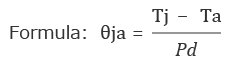
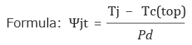
- ψjt:Thermal characterization parameter between junction temperature Tj and package mark surface center temperature Tc(top)
- θjc:Thermal resistance between junction temperature Tj and case Tc(bot)
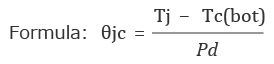
- Pd:power dissipation of the IC
-
Thermal resistance measurement support
We measure the thermal resistance value on the customer's actual board and provide
Thermal resistance (θja, ψjt), Transient thermal characteristic graph and so on.
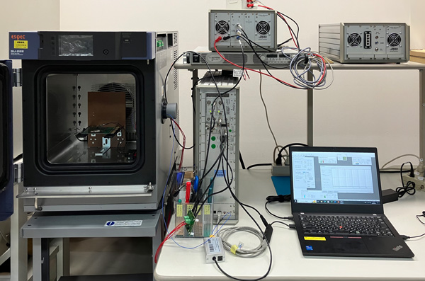
Nisshinbo Micro Devices utilizes Siemens' Simcenter (T3STER), a high-accuracy de facto standard transient thermal tester, to provide measurement results of thermal resistance on customer's actual board or actual board prepared by Nisshinbo Micro Devices.
Transient thermal characteristic graph
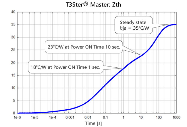
We measure transient thermal characteristics on customer's actual board. The transient thermal characteristic graph shows the thermal resistance of power application time when the customer uses it.
Simcenter T3STER Master: Zth
Measurement principle of transient temperature measurement system Simcenter T3STER
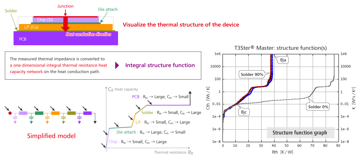
The thermal impedance measured by the transient temperature measurement system Simcenter T3STER is converted into a one-dimensional integral thermal resistance heat capacity network on the thermal conduction path. θja can be calculated from the integral structure function. Also, θjc can be calculated by measuring samples with different amounts of solder. Furthermore, ψjt can be measured using a thermocouple.
For thermal simulation and measurement of thermal resistance using actual board, please contact our sales representative or distributors.