


Operational Amplifier Basics – Types and Characteristics in Detail -
Operational amplifiers (op amps) are one of the most basic and most important components in the electronics products we use today.
This page explains the operation, their types and main external circuit components, usage, and some specific applications of op amps.
It is useful not only for those who have just started learning about electronic circuits or for design novices who have just begun circuit design, but also for those who want to review the fundamentals of op amps.
What Is an Operational Amplifier? (Principle and Necessity)
-
The word op amp is an abbreviation for Operational Amplifier, or in Japanese, arithmetic amplifier.
An op amp is an integrated circuit (IC) that can amplify weak electrical signals.
-
Principle of Op Amps
-
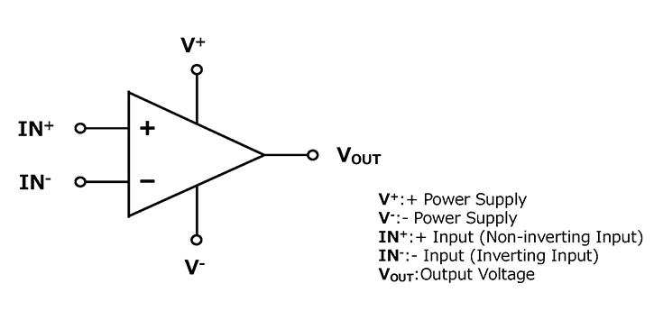
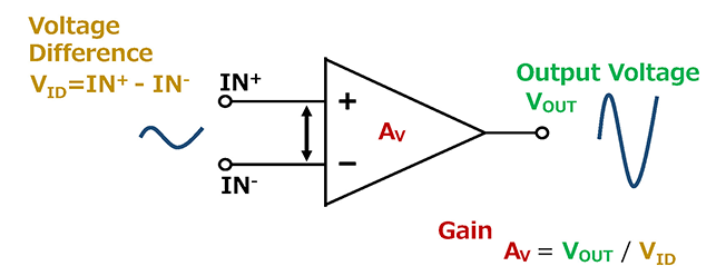
An operational amplifier has two input terminals and one output terminal in addition to the power supply terminals.
One of these two input terminals is called IN+, + input, or non-inverting input, while the other is called IN-, - input, or inverting input.
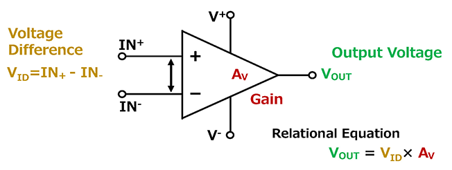
The most basic operating principle of an operational amplifier is that the voltage difference between these two input terminals is amplified and output.
Specifically, the difference between the voltages given to the two terminals IN+ and IN- is amplified inside the operational amplifier and output.
The degree of amplification is called the amplification factor, or gain (Av). The relationship is shown by the equation in the figure below. The gain in the figure is usually determined by the characteristics of the operational amplifier itself and is also called open-loop gain*.
-
When used in open loop (open state), the output always sticks to the maximum (high) or minimum (low), acting like a comparator.
*Open-loop Gain: The DC signal gain of an operational amplifier with no feedback circuit connected.
Why Do We Need Op Amps?
-
Why do we need op amps in the first place?
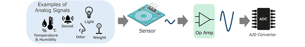
We are surrounded by many analog signals in our daily lives. We humans can directly feel and sense these analog signals. We use sensors to read these analog signals in nature and make use of them for a better life.
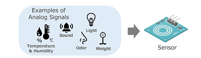 Read Analog Signals with Sensors, etc.
On the other hand, we now use computers, smartphones, and many other devices that handle digital signals.
-
Unlike continuous, uninterrupted analog signals, digital signals have the advantage of being able to represent signals as a code, making them resistant to noise and errors, and they can be compressed/expanded, making them excellent for processing information.
However, most of the information in nature is analog signals. Therefore, when using digital devices, the analog signals input to them must be converted to digital signals.
-
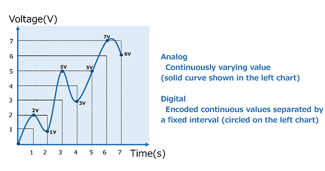 Analog is a continuous value like a line.
Digital is a (discrete) value that is separated like a point.
In addition, most of the output signals (analog) from the aforementioned sensors that read analog information from the natural world are low power.
Directly replacing this sensor's signal with a digital signal will distort the signal. The signal may also be noisy, or conversely, it may be too loud.
If calculations are made using these distorted signals (signals that are not in the desired state), the operation cannot be expected to be as designed.
This is where op amps come in.
By converting the signal output from the sensor into an appropriately sized signal with minimal distortion using an operational amplifier, and then replacing it with a digital signal using an A/D converter, it is possible to achieve the expected operation as designed.
 Inserting an Op Amp to Convert into Appropriate Signals
The same is true when converting from digital to analog.
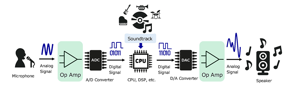
The signal output from a digital device is a digital signal consisting of a series of “0”s and “1”s. To make this into a signal that humans can understand, it must be converted into an analog signal using a D/A converter.
Operational amplifiers are sometimes used to convert the digital signal to an analog signal, too.
The following is an example of karaoke equipment. The voice input from the microphone and the performance of musical instruments are combined to form a single piece of music, which is output from the speakers and played in our ears.
Functions, Characteristics, and What Op Amps Can Do
Functions of Op Amps
What are some of the functions of an operational amplifier?
Four typical ones are described below. (Images are for illustrative purposes only)
-
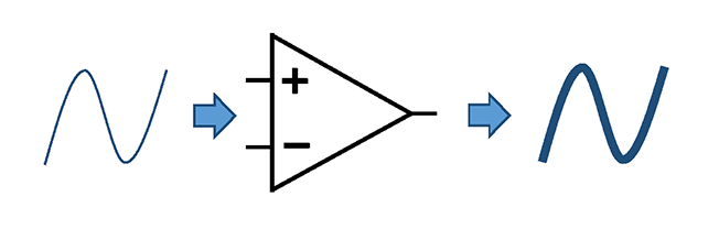
Amplification: Amplifies a small input signal into a larger one and outputs it. (Small amplitude to large amplitude)
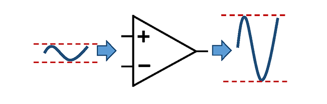 Amplify Signal Amplitude
-
Filtering: Removes unnecessary signals from the input signal and outputs only the necessary signals.
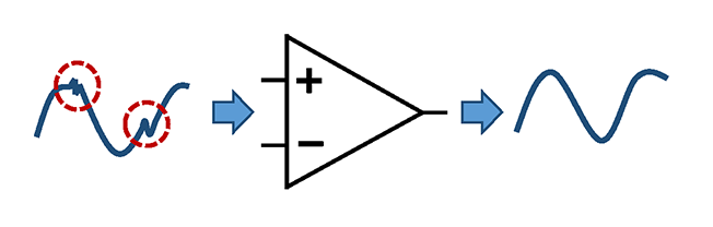 Remove Unnecessary Signals
-
Comparison: Compares two voltages. (works like a comparator).
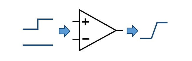 Compare Two Signal Levels
-
Buffering: Enhances the amount of power, such as small-current sensor signals, through operational amplifiers.
 Enhances Current Drive Capability
Next, let us discuss the characteristics of op amps.
Characteristics of Op Amp
High Amplification Factor (Gain)
-
One of the characteristics of operational amplifiers is their extremely high amplification factor, or gain.
The gain of operational amplifiers is usually said to range from several hundred thousand to several million. This means that even very weak input signals can be greatly amplified and output.
Because of this high gain, operational amplifiers are used in a wide variety of applications.
For example, they can amplify weak audio signals in audio equipment or amplify weak signals acquired from sensors to make them easier to read.
-
High Input Impedance
-
Op amps have very high input impedance*.
*Impedance: a resistance that impedes the flow of current.
The higher the impedance of a device or circuit, the less current will flow into that device or circuit.
The fact that an op amp has a high input impedance means that very little current can flow into the input terminals of that op amp.
This characteristic allows the op amp to amplify the signal of its preceding signal source (the sensor in the diagram) without distortion.
In short, it has the advantage that the signal source can effectively transmit its signal further to other parts of the circuit without wasting unnecessary energy. 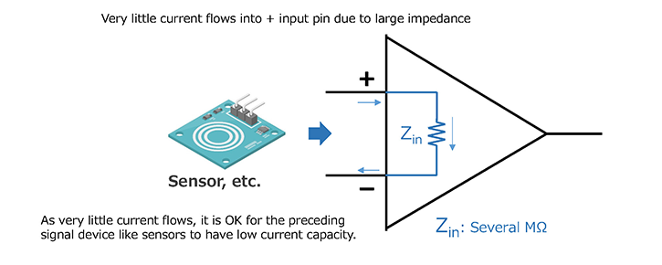 High Input Impedance
Since very little current flows into the input stage of the op amp, devices such as sensors can have low current capability.
Low Output Impedance
-
Op amps are characterized by their low output impedance. It means that the op amp can effectively supply a lot of current.
With low output impedance, the supply of current from the output terminals is not affected by the size of the connected load, so the signal is delivered to the load in the subsequent stage without distortion.
This means that the op amp can supply more current directly to the load, allowing it to provide power to a variety of loads while maintaining signal accuracy. 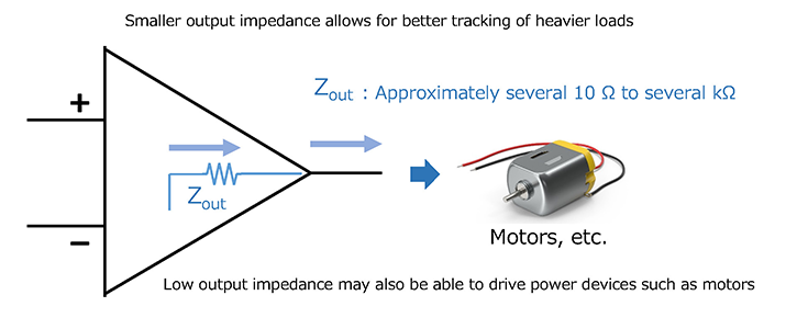 Low Output Impedance
There are several concepts specific to operational amplifiers.
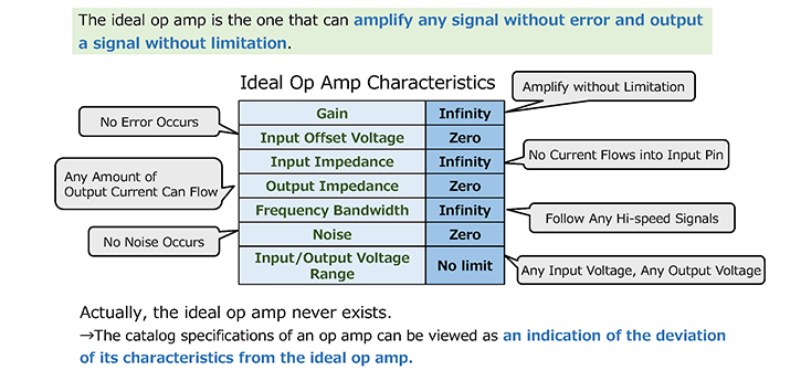
The Ideal Op Amp
The ideal op amp amplifies the voltage difference between the two input terminals to infinity. This means that the gain is infinite. Also, the output impedance is zero and the input impedance is infinite.
When designing a circuit using op amps, understanding the concept of the ideal op amp will make it easier to understand the operating principle of the circuit.
The initial design phase of a circuit is often based on the characteristics of an ideal op amp (infinite bandwidth, gain, very high input impedance, etc.) and then adjusted based on realistic parameters.
Knowing the characteristics of the ideal op amp also makes it easier to spot problems when the designed circuit does not behave as expected, and analyzing the difference between the real and ideal characteristics makes it easier to identify the cause of the problem.
Virtual Short (Imaginary Short)
When you look up operational amplifiers, you will probably see the term virtual short*.
This virtual short is another very important concept in understanding operational amplifiers.
*Virtual short is also known as imaginary short.
Virtual short literally means a virtual short circuit, and it refers to the fact that the + input (non-inverting input terminal) and the - input (inverting input terminal) of an operational amplifier are at the same electric potential even though they are not actually connected. This means that the inputs appear to be short-circuited to each other.
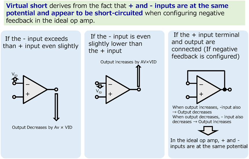
It is important to understand this concept of virtual short in circuit design using operational amplifiers.
What Op Amps Can Do
-
Now that we have introduced the functions and features of operational amplifiers, what can we do with an operational amplifier with these functions and features?
To make it easier to imagine, let's start with an example.For example, if we compare an op-amp to a human body part, it would be the analog brain. On the other hand, other parts of the body, such as the eyes, ears, nose, and other parts that sense the five senses, can be compared to sensors.
The op amp, which is the brain, receives analog signals from the eyes, ears, nose, skin, tongue, and other sensors, converts them into various types of signals, and processes them. Sometimes it even emits voice from its mouth (speakers) or moves its arms and legs (motors).
-
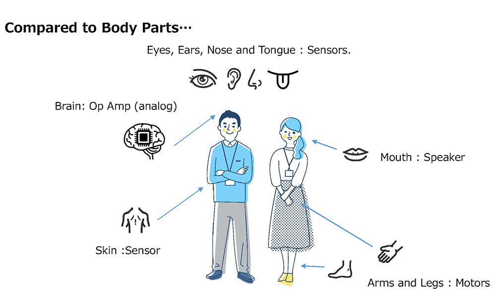
Thus, op amps can process various signals in various ways and output them.
They can invert input signals, perform arithmetic operations such as addition, subtraction, multiplication, differentiation, integration, oscillate signals, and amplify currents.
Op Amp Usage and Circuit Examples
Op Amp Usage
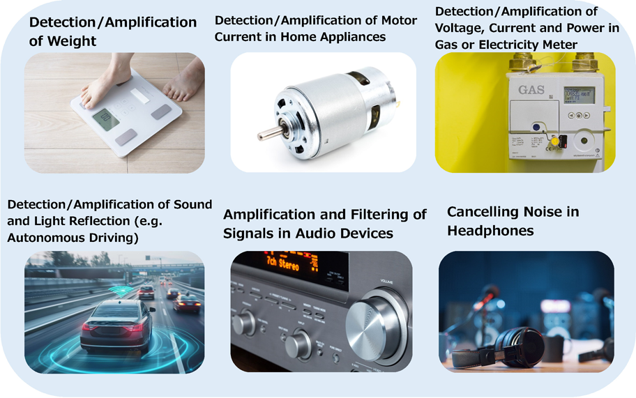
In what areas of our lives are op amps used?
Op amps are mainly used to amplify sensor/audio signals and to quantify power. In our daily life, operational amplifiers are used in the following areas.
Typical Circuit Examples Using Op Amps
The following are typical amplification circuits of op amps and their gain formulas.
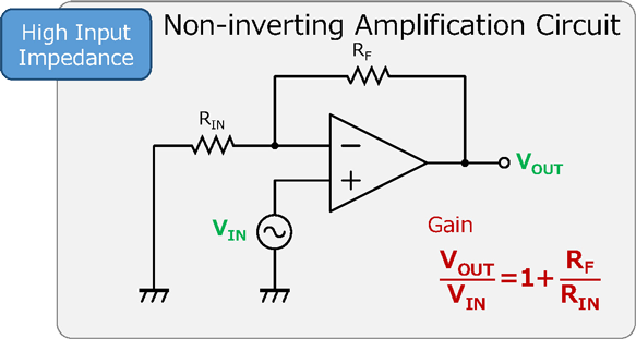
Non-inverting Amplification Circuit
-
A non-inverting amplification circuit amplifies the input signal without inverting it.
This circuit has two resistors (RIN and RF) between the output signal (VOUT) and GND, and the voltage divider of these resistors is input to the – input terminal.
The input signal (VIN) is connected to the + input terminal of the op amp. This circuit has the feature that the input and output signals are in phase.
-
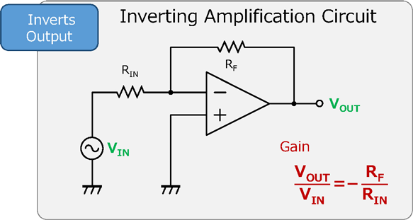
Inverting Amplification Circuit
-
The inverting amplification circuit inverts the phase of the input signal and amplifies it. It has two resistors (RIN and RF) between the input signal (VIN) and the output signal (VOUT), and the voltage divider of these resistors is input to the – input terminal.
GND is connected to the + input terminal. This circuit is characterized by the fact that the phase of the input and output signals are reversed.
-
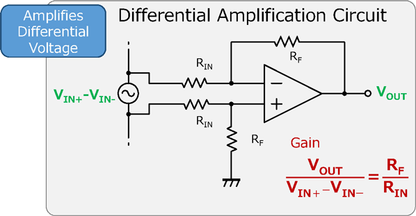
Differential Amplification Circuit
-
The differential amplification circuit of an op amp amplifies the difference between two input signals.
The input signals are connected to the + and - input terminals of the op amp, and the differential input signals are amplified inside the op amp.
The output signal is controlled using a feedback circuit, and the difference between the input signals is output as the gain.
This circuit can reduce the effect of common mode noise* entering the terminals.
*Common mode noise: Electromagnetic interference or noise that commonly appears in two or more signal lines or transmission lines.
-
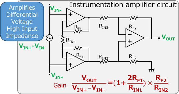
Instrumentation Amplifier Circuit
-
Instrumentation amplifier circuits are amplifier circuits used for measurement and control purposes, mainly in industrial equipment.
Instrumentation amplifiers amplify small input signals with high precision and minimize common mode noise.
Instrumentation amplifiers are used to amplify weak signals from sensors and are widely used in measurement and control systems.
-
Types and Selection of Op Amps
Types of Op Amps
There are many types of op amps and many different ways to classify them.
-
Classification by Process [Bipolar Process] - Low Input Impedance
- High Withstand Voltage
- Low Low-frequency Noise
- Large Current Consumption
- *Compared with CMOS Process
[CMOS Process] - High Input Impedance
- Low Withstand Voltage
- High Low-frequency Noise
- Low Current Consumption
- *Compared with Bipolar Process
-
Classification by Input/Output Stage Configuration [Dual Supply] - Low Distortion Ratio
[Single Supply] - Rail-to-Rail Output
- Rail-to-Rail Input/Output
-
Classification by Characteristics [High Accuracy] - Low Offset Voltage
[High Speed Wide Bandwidth] - High Slew Rate and Gain Bandwidth (GBW)
[Low Power] - Low Supply Current
[High Output Current] - High Output Current
[Low Noise] - Low Equivalent Input Noise Voltage
-
Classification by Characteristics [High Withstand Voltage] - High Supply Voltage Rating
[Low-Voltage Operation] - Low Minimum Operating Voltage
[Small Package] [Automotive Applications] [High EMI Immunity] - Tolerant to High Frequency Noise
Selection of Op Amp
Since there is no such thing as an ideal op amp in this world, op amps in circulation are often characterized by some characteristics.
Therefore, it is necessary to select the right op amp for each application. Following items are the main parameters and conditions to consider when choosing an operational amplifier.
-
Select by Supply Voltage
When choosing an op amp, it is very important to consider the supply voltage. It must be ensured that the op amp will operate properly within the range of the power supply to be used.
In particular, you must choose op amps with high absolute maximum ratings and high withstand voltages so that they will not be destroyed if the supply voltage is high.
On the other hand, for low supply voltage applications, an op amp that operates properly at low voltages must be selected.
Also, if you want the output to be close to the upper and lower limits of the power supply within the supply voltage range, you must also choose an op amp with rail-to-rail operation.
-
Select by Noise Performance
It is very important to consider noise performance when using op amps at high amplification levels.
Although op amps amplify signals, they may also amplify noise, which will adversely affect the system.
Therefore, it is important to make sure that the noise level is below the required level.
-
Select by Current Consumption
If you are considering battery-powered applications, such as portable devices or mobile applications, the current consumption of the op amp you select is very important.
Low current consumption also reduces heat generation, so low-consumption op amps are needed for high-density circuits and small devices.
-
Select by Terminal Configuration and Package
Common (general-purpose) op amps used in many applications are available in the same package and with the same terminal configuration for availability. This is because there are several products of the same package size and terminal configuration with similar characteristics that can be quickly replaced by other op-amps in the event that the op amp in use is suddenly unavailable due to a delay in production or discontinuation.
Using such common op amps allows replacement to proceed smoothly even in the unlikely event of trouble.
Also, for applications with small boards, such as mobile applications, op amps in small packages are useful.
Select by Other Characteristics
-
High-speed / Wide Band
For applications that require signal processing at high frequencies or fast response, high-speed, wide band op amps, which have broad bandwidth characteristics, is the choice.
-
For Automotive Applications
Compared to op amps for general use, automotive op amps require higher durability and reliability, such as a wider operating temperature range and support for higher voltages.
We offer a lineup of products that meet international reliability standards such as AEC-Q100, as well as our own in-vehicle quality products.
-
High Precision
Applications such as high-precision measurement and sensing, control systems, and data conversion, which require accurate signal processing, demand high-precision op amps.
In particular, they offer low offset voltage, low drift, high common-mode rejection ratio (CMRR), high power supply rejection ratio (PSRR), and high open-loop gain.
-
For Industrial Applications
Op amps for industrial equipment must meet strict specifications, such as high speed and high precision, and must be supplied stably over a long period of time.
We offer product longevity program (PLP).
Characteristics of Op Amps
Electrical Characteristics of Op Amps
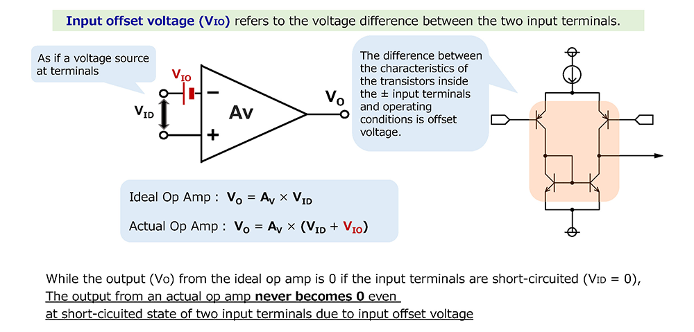
Input Offset Voltage
The input offset voltage (also called VIO or VOS) of an op amp refers to the minute voltage created between the two input terminals (+ input and - input) of the op amp. Theoretically, there should be no voltage difference between the input terminals in order for the output of an op amp to be zero.
However, in an actual op amp, a minute voltage difference exists between the input terminals. This is the input offset voltage. A minute imbalance in the manufacturing process or imperfect matching of circuit elements can cause a minute voltage to be generated between the input terminals. This value is typically on the order of (µV) to (mV).
Large input offset voltages can cause errors in the output signal. Usually, this effect is small and is minimized by design and compensation circuitry, but it may not be completely zero. This input offset voltage can be a problem, especially when dealing with DC signals or in applications where high precision is required. For this reason, some op amps have an offset adjustment terminal to adjust this.
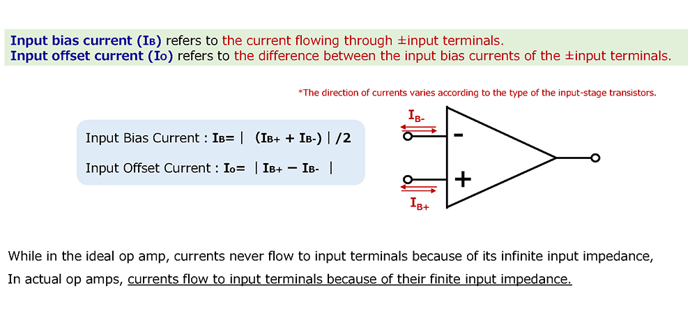
Input Bias Current and Input Offset Current
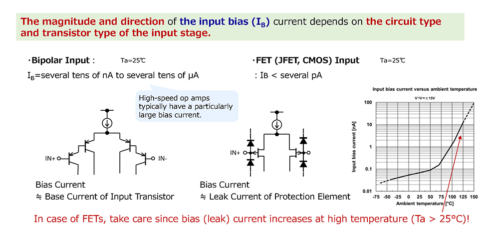
The input bias current (also called IB) of an op amp is the DC current that normally flows through the + or - input terminals of an op amp.
It flows as the base current of the op amp's input transistor (bipolar input) or as the leakage current of a protection device (FET input).
In an ideal op amp, the input impedance is assumed to be infinite and therefore the bias current is zero, but in a real op amp, there is a small bias current at the input terminals because the internal transistors require a small base current (in the case of bipolar inputs).
The input bias current also varies with temperature and time. If the input bias current is high, its effect may cause errors in the output of the op amp.
On the other hand, the input offset current (also called Io) is the difference in input bias current between the + and - input terminals of an op amp.
Ideally, these input terminals should be at the same electric potential, but imbalances in the manufacturing process and differences in device characteristics can result in minute currents.
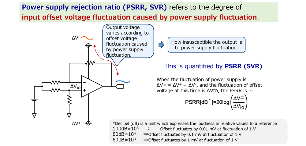
Power Supply Rejection Ratio
The power supply rejection ratio (PSRR*) of an op amp is a measure of how insensitive an op amp is to variations in supply voltage. PSRR is usually expressed in decibels (dB). The higher the PSRR, the better the op amp performs, with less offset voltage variation dependent on supply voltage.
On the other hand, if the PSRR is low, the supply voltage-dependent offset voltage variations directly affect the output of the op amp, potentially distorting the input signal.
*Also called SVR (Supply Voltage Rejection)
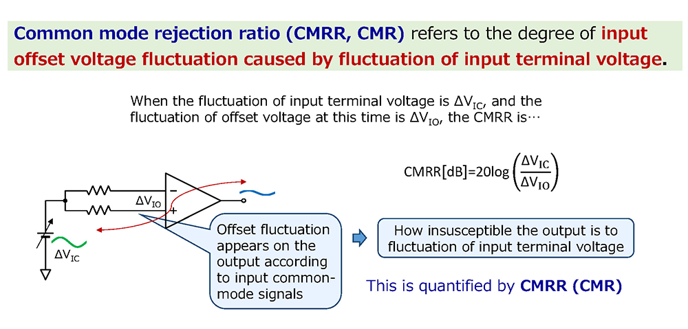
Common-Mode Rejection Ratio
The common-mode rejection ratio (CMRR or CMR) of an op amp indicates the sensitivity of the op amp to common-mode signals.
An op amp amplifies the difference between the + and - input terminals, so if a common-mode signal is input to both terminals, the output of an ideal op amp never varies because there is no difference.
However, the actual op amp circuit has an input offset voltage due to asymmetry or imbalance of the internal elements, so the offset variation according to the in-phase signal will appear at the output.
An op amp with high CMRR performance suppresses common-mode noise and other external in-phase signals, and only the differential signal is amplified, thus improving signal accuracy.
CMRR is generally expressed in decibels (dB), with higher values indicating better performance.
Equivalent Input Noise Voltage
The equivalent input noise voltage of an op amp is a measure of how much noise is generated at the input elements of an op amp.
An op amp consists of several tens of elements. Most of the noise in an op amp appears at the output as a characteristic of the differential pairs in the input stage.
The other elements have a structure that makes it difficult for noise to appear at the output. Therefore, when an op amp is operated with a large gain by adding an input DC signal, an AC signal will appear at the output.
This AC signal becomes a noise signal in the input stage of the op amp. The AC signal at the output divided by the gain set by the feedback circuit becomes the input equivalent noise voltage. This value is usually expressed as (μVrms) or (nV√Hz).
Open-loop Voltage Gain
The open-loop voltage gain is the ratio of the output voltage to the input voltage when the op amp is operating without feedback.
It is a measure of how much an op amp can amplify a signal without feedback. This value is usually expressed in decibels (dB); the higher the open-loop voltage gain, the higher the op amp's gain.
Gain-Bandwidth Product
The gain-bandwidth product (also known as GBP) of an op amp is a measure of the relationship between the gain (amplification factor) of an op amp and its operating bandwidth.
The gain-bandwidth product is the product of the op amp's gain and its operating bandwidth, usually expressed in Hertz (Hz).
The gain (amplification factor) and the operating bandwidth (frequency range) of an op amp are generally inversely related. In other words, the higher the gain, the narrower the frequency range, or bandwidth, over which the op amp can operate effectively. Conversely, the wider the bandwidth, the smaller the gain.
Slew Rate
Slew Rate indicates how quickly an op amp can change the voltage of its output signal in response to an input signal. The larger this number, the faster the op amp's response time.
In other words, an op amp with a high slew rate characteristic can quickly follow a rapidly changing input signal, while an op amp with a low slew rate characteristic cannot change rapidly and cannot quickly follow the input signal. As a result, the output signal may be distorted.
List of Op Amp Terms
The following is a list of terms commonly used in op amps.
| Terms | Explanation |
|---|---|
| Non-inverting Input terminal | This is the input terminal marked with the symbol “+”, “VIN+”, “IN+”, “+INPUT”, etc. on the op amp. Normally, this terminal is controlled by a voltage. This terminal is controlled by comparison with the voltage input to the inverting input terminal. |
| Inverting Input terminal | This is an input terminal marked with the symbol “-”, “VIN-”, “IN-”, “-INPUT”, etc. on the op amp. Normally, this terminal is controlled by a voltage. This terminal is controlled by comparison with the voltage input to the non-inverting input terminal. |
| Gain | Gain is also expressed as amplification factor. An op amp amplifies signals input to its - and + inputs, and gain is an important parameter that indicates its ability to amplify. Note that when the term gain is used in op amps, it refers to voltage gain. |
| Open-loop Gain | Open-loop gain refers to the gain of the DC signal of an op amp with no feedback circuit connected. In an ideal op amp, this value is close to infinity, but in a real op amp it has a finite value. Open-loop gain is rarely used in real applications and is often used to understand the basic characteristics of op amps. |
| Closed-loop Gain | Closed-loop gain is a gain set by returning some signal from the output of the op amp to the input through a feedback loop. The output of the op amp is then controlled based on the input signal and adjusted to a predetermined gain to stabilize the output. The closed-loop gain depends on the circuit configuration. |
| Feedback Resistor | The feedback resistor is a resistor connected from the op amp output to the inverting input. The output signal is returned to the input through this resistor, which determines the gain as a closed loop. |
| Negative Feedback | Negative feedback is the technique of returning the signal from the output of an op amp to the inverting input, and a feedback resistor is usually inserted in this path. A portion of the output is returned to the input side through this resistor, which determines the overall gain of the op amp and is one of the key techniques that allow the op amp to operate stably. |
| Rail-to-Rail | Rail means supply voltage, and a rail-to-rail op amp is an op amp designed to operate over the entire so-called supply voltage range (highest to lowest voltage), from the highest rail to the lowest rail (also called a full swing op amp). Unlike dual or single op amps that can operate only up to the common-mode input voltage range, rail-to-rail op amps can operate over the full range of their supply voltage. Some have rail-to-rail inputs or outputs, while others have both rail-to-rail inputs and outputs. |
| Bandwidth | Bandwidth is the range from the lowest frequency to the highest frequency over which an op amp can operate and amplify signals. |
| Virtual Short | Virtual short means the non-inverting input terminal and the inverting input terminal are at the same electric potential even though they are not actually connected, making it appear as if the two input terminals are shorted together. This is a very important concept in understanding op amps. |
Frequently Asked Questions on Op Amps
For more information on various functions of op amps and frequently asked questions, please refer to the FAQs below.
Frequently viewed “FAQs”
- Could I get IBIS model for an analog IC( op amp or regulator )?
- What is input bias current of OP-Amp or Comparator?
- Why does it occur op amp output phase-reversal phenomenon?
- The input resistance of the operational amplifier is low and the input voltage seems to drop. <br> How much ohms is the value of the input resistance of it?
- Does Nisshinbo Micro Devices available Rail to Rail Op Amp?