


Volume 4 Measures for Trouble in Li-ion Battery Protection Circuits

In volume 4, I would like to talk about troubles occurring in Li-ion battery protection circuits. Thanks to the long experience in Li-ion battery protection circuits, I think we can provide protection ICs that give customers safety and security now. Reaching this level of service, however, required us to overcome a lot of difficulties, and we have developed and evolved our products every time we have been confronted with an array of problems. I will show you some examples and explain what kind of countermeasures are installed on protection ICs.
★
Measures against Electromagnetic Noise
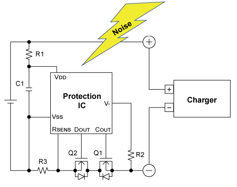
One of the applications that brought up the Li-ion battery market largely is mobile phones. As a mobile phone sends and receives electromagnetic waves, its battery pack is always in an environment with electromagnetic noise. At the beginning of Li-ion batteries, this electromagnetic noise was a serious problem because it led to the misdetection of protection circuits.
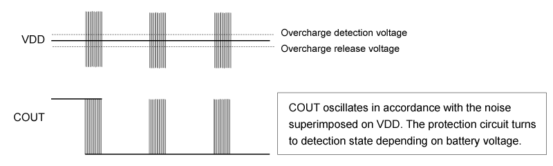
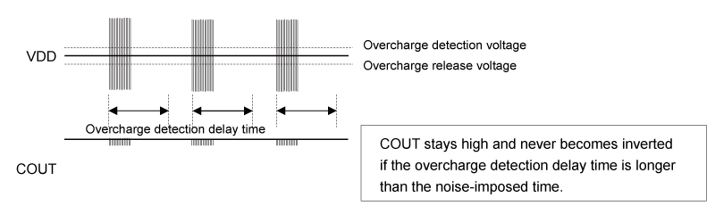
An overcharge detection circuit did not have a delay circuit for detection and release at that time, and the output inverted in a short time of 20 to 30 µs after the inversion of the comparator for overcharge detection. In such a circuit, electromagnetic noise causes fluctuations of the reference voltage and voltage sense node input to the comparator, by which the output becomes inverted despite the battery voltage not reaching the overcharge detection voltage. As a result, the circuit turns to overcharge detection state at a battery voltage close to its full capacity (but not fully charged), and charging operation stops before the battery fully charged. In addition, electromagnetic waves are emitted periodically from the mobile phone according to the communication method it adopts, so the output from the protection IC also oscillates periodically. In the worst case, the FET was damaged by the heat generated at certain frequencies. Through the experience of these failures, it has been common to set a delay time for each detection circuit inside a protection IC.
Without delay time for overcharge detection
With delay time for overcharge detection
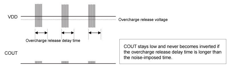
The problem never ended only with false detection; false release also became problematic later. A battery pack detecting overcharge done by an abnormal charger stops charging operation even when a charger is connected, as a matter of course. However, there occurred a phenomenon that applying an electromagnetic wave to the battery pack at this state could restart charging operation. This is just the opposite to false detection, namely, false release. Once such a phenomenon happens, charging operation continues in spite of the overcharge being detected, the battery voltage rises beyond the overcharge detection voltage, and the battery falls into a dangerous situation due to being overcharged. To solve this problem, a delay time was also added to release from overcharge.
Without delay time for release from overcharge
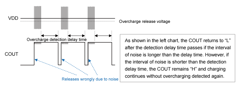
With delay time for release from overcharge
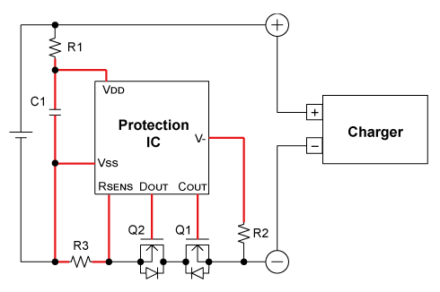
As mentioned above, contemporary protection ICs have as many countermeasures against noise as possible. The resistivity against electromagnetic noise, however, also depends on the layout of the protection circuit board. Long wiring for pins such as the VDD for voltage monitoring, the V- and Rsense for current monitoring, will work as an antenna and make the board vulnerable to noise. Therefore, please locate external components as close to the protection IC as possible to shorten the wiring drawn red in the following figure.
★★
Measures against Reversely Connected Charger
Today’s mobile devices such as phones and laptop PCs contain a Li-ion battery which cannot be detached in many cases. In the past many of Li-ion batteries used inside battery-powered applications were detachable. Securing safety considered, mechanical measures were taken to prevent the positive and negative terminals of a charger from being connected reversely. Nevertheless, we conducted evaluations for reverse connection to be ready in any chance.
The withstand voltage of our protection ICs are up to 30 V. This value is derived from the battery voltage of 24 V used in lorry trucks with some margins considered. The harshest condition of reverse charge testing adopted application of reverse connection with 30 V. If an FET with low withstand voltage is used, connecting a 30 V reversely causes short and damage between the source and gate of the FET, which can lead to dangerous situation of heat generation and firing. To prevent this, firstly, a protection diode is inserted between the source and gate of the FET to clamp the gate-source voltage with the Vf of the diode. In addition, a current limit resistor is necessary between the gate of the FET and the pin of the IC to stop a large current from flowing to the IC. These measures enable the protection circuit to avoid heat generation and firing even at reversely connected charging of 30 V.
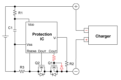
As mentioned above, many of Li-ion batteries used in today’s mobile devices are undetachable, and the charging terminal is covered by something. Although it is worth considering how much effort you will make to take measures against reverse connection, the circuit above will be informative if you have to consider the case where a charger is connected reversely.
★★★
Operation at Power-on
Although this is not a trouble related to protection ICs, one of the important problems is the state of the protection IC at power-on at the first connection of the protection circuit and the battery cell. We often receive inquiries about this problem from customers even today.
The operation of a protection IC at power-on depends largely on its specifications. Which specification matters most is the release type from overdischarge state. There are roughly two types: auto release type and latch type. The auto release type determines its output simply by the battery voltage value. The output turns off at overdischarge in which the battery voltage falls below the overdischarge detection voltage, and turns on at release from overdischarge state when the battery voltage becomes higher than or equal to the overdischarge release voltage. On the other hand, as release conditions, the latch type requires not only that the battery voltage be higher than or equal to the release voltage but also that a charger be connected. This means that once overdischarge is detected, the latch type can never be released from overdischarge state unless a charger is connected to the protection circuit regardless of the battery voltage reaching the release voltage.
Then, how does the difference between the two release types affect the operation at power-on? To begin with the auto release type, when a battery cell is connected to the protection circuit for the first time, its output turns on at the battery cell voltage higher than or equal to the overdischarge release voltage. For example, the nominal cell voltage of 3.7 V can certainly turn on the output, and end-users can use the battery pack as soon as they receive it. On the other hand, once the latch-type protection IC powers on with overdischarge detection state when connected to a battery, a charger is required to release the state. Therefore, users cannot use the battery unless they connect the battery to a charger.
-
Overdischarge release: auto release type
-
Overdischarge release: latch type
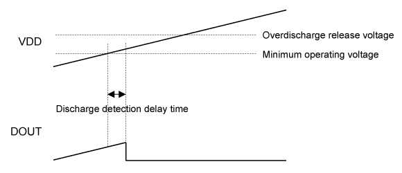
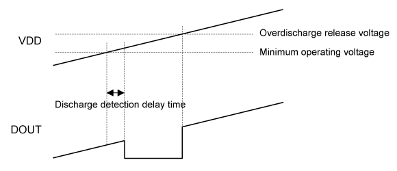
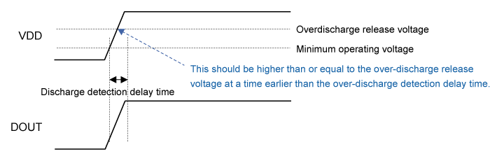
Whether the IC powers on with overdischarge state or not depends on the speed of the VDD voltage increase from the protection IC perspective. The protection IC turns to overdischarge state by overdischarge remaining longer than the detection delay time. The delay time is configured by ICs; in the case of 20 ms, for instance, the latch-type IC will never power on with overdischarge state if the VDD voltage rises from the minimum operating voltage to the overdischarge release voltage within 20 ms. As a result, the output starts on, and the battery pack is usable immediately.
The VDD voltage increase speed is the point to make a latch-type protection IC certainly start up with the output on. If you would like to do so, pay attention to connected components such as capacitors, as they are the cause of slowing down the speed.
To start up with output ON state using overdischarge release latch-type
★★★★
In this volume, I introduced three cases that might be troubling for customers’ evaluation, but various know-hows are necessary to make full use of Li-ion battery protection ICs. We have long experience and a lot of achievements in Li-ion battery protection ICs, so please inquire to us through our website if you have any questions.
In the next and last volume of this series, I will talk about the future of protection ICs, with the perspectives of post-Li-ion batteries considered.
Published May 16, 2023
Serial Content
Will Li-ion Battery Protection ICs Never Perish?
-
Future of Li-ion Battery Protection ICs
-
Measures for Trouble in Li-ion Battery Protection Circuits
-
Changes in Applications Using Li-ion Batteries -Customer Transition along with Application Expansion-
-
History of Li-ion Battery Protection ICs -Evolution of Performance and Package from Beginning to Present-
-
History of Li-ion Battery Protection ICs -Evolution of Functions from Beginning to Present-
-
-The Pioneer Says...- Will Li-ion Battery Protection ICs Never Perish?
Author profile

Akihiko Fujiwara
Nisshinbo Micro Devices Inc.
Akihiko Fujiwara was engaged in the planning and design of our Li-ion battery protection ICs beginning in the 1990s, during the early days of rechargeable Li-ion batteries, and earned a strong reputation in the industry. As an "expert in battery protection ICs," he was also involved in marketing and strategic planning. By continuously monitoring worldwide trends in batteries and battery protection ICs, he helped lead the direction of Nisshinbo Micro Devices' battery protection IC business.