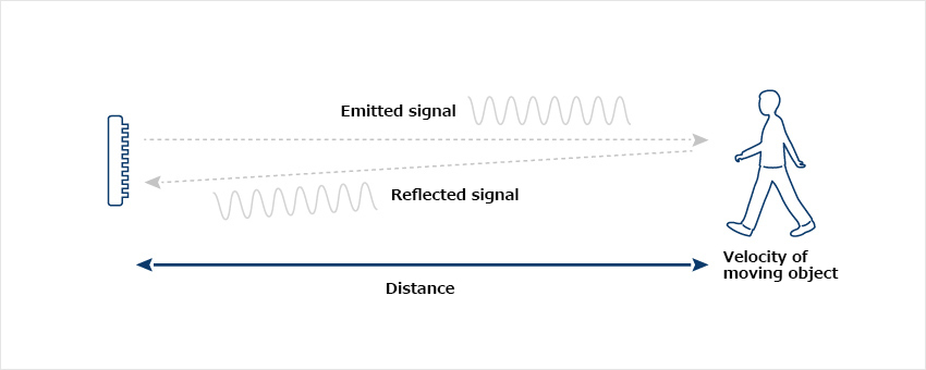
A Doppler sensor can detect the velocity of a moving object and, from the presence/absence of a Doppler signal, the presence of an intruder. The microwaves emitted from the sensor bounce back if there is a reflective object in the path. The phase difference between the transmitted signal and the reflected signal provides the frequency that expresses the object’s velocity. This is called the Doppler or beat frequency. This Doppler signal is processed by circuitry called an IQ detector and from its phase it is possible to determine whether the reflective object is approaching or receding.
Doppler Sensor Principle
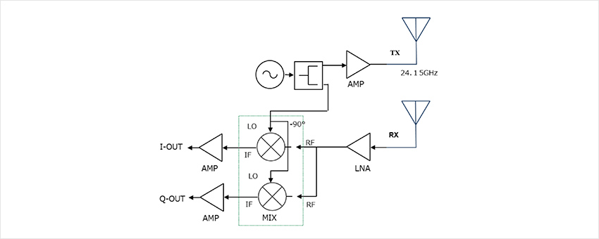
The signal generated by an oscillator is what is transmitted. Part of this is handled as the local signal on the receiving side so as to construct a phase detector. The local signal is divided into two signals, so that each output has a phase difference of 90°. Radio waves emitted from the transmitting antenna are reflected back to the receiving antenna if there is a reflective object in the path.
This weak signal is amplified using an LNA (low-noise amplifier) and the beat signal (IF signal) is produced by the phase detector (IQ mixer). The frequency of this beat signal represents the object’s velocity, and from the magnitude of the signal it is possible to determine the distance to the moving object. The phase state of the IQ signal varies depending on the way the signal is reflected, making it possible to determine whether the object is approaching or receding.
Doppler Sensor Functional Block Diagram
In the case of the Doppler method, a CW signal is emitted.
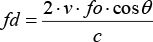
The beat signal, or Doppler signal, that is output has a frequency proportional to the velocity of the moving object (target).
The beat signal (fd) is derived as follows:
*CW stands for continuous wave
fd: Doppler frequency (Hz)
V: Velocity of the target (m/s)
fo: Emitted signal frequency (Hz)
c: Speed of light 3 x 10⁸ (m/s)
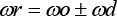
θ: Angle between the direction in which the target is moving and the direction of observation
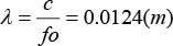
Since this sensor transmits in the 24 GHz band, fd (Doppler frequency) = 2v / 0.0124 m can be derived from the following equation:
The received frequency is indicated as "+" when the target is approaching, and as "-" when it is receding. It is expressed as an angular frequency thus:
This sensor uses an IQ phase detector to output two Doppler signals (I output / Q output) whose phase differs by π/2 from the signal reflected back from the object. When the target is approaching, the I output is a Doppler signal which is advanced by π/2 from the Q output; conversely, when the object is receding, it is delayed by π/2. Thus it is possible, using signal processing, to determine if the target is approaching or receding from whether the phase difference is advanced or delayed.
The magnitude of the reflected signal is used for intrusion detection employing the voltage amplitude. Here too, the Doppler frequency can be used to measure the velocity of a moving intruder. However, in the case of a stationary person there will not be any Doppler signal output.
* Doppler is not output at cos 90° * Velocity needs to be corrected for measurement angle.
Doppler Sensor Features
It is possible to determine the velocity of an object from the Doppler frequency.
It is possible to detect whether an object is approaching or receding from phase difference data.
Using multi-frequency Doppler, it is possible to measure the distance to moving objects.