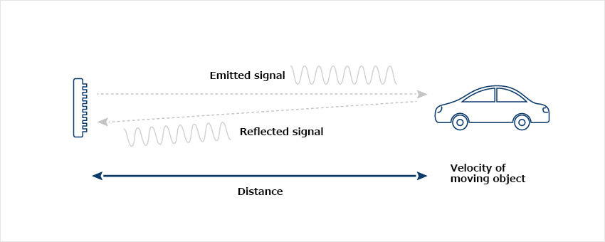
A CW signal is transmitted in the case of the FSK Doppler method. However, the Doppler signal is obtained by switching two frequencies at a fixed interval. As with the conventional Doppler method, the Doppler beat signal generated in this case has a frequency the depends on the velocity of the target.
FSK Doppler Sensor Principle
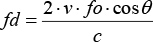
The beat signal (d) is derived as follows:
fd: Doppler frequency (Hz) V: Velocity of the target (m/s) fo: Emitted signal frequency (Hz)
c: Speed of light 3 x 10⁸ (m/s)
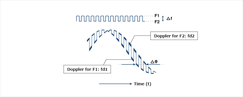
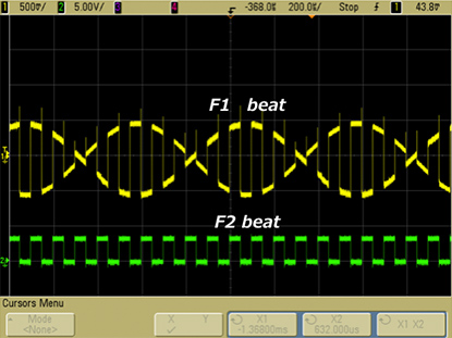
θ: Angle between the direction in which the target is moving and the direction of observation F1 and F2 are generated by switching between two frequencies. Depending on the distance, the Doppler signal will demonstrate a phase difference, as shown in the diagram below. The method by which the distance is calculated from this phase difference is called FSK (frequency shift keying) Doppler.
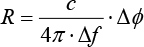
The distance is obtained from the phase difference between fd1 and fd2 thus:
※ φ (rad)
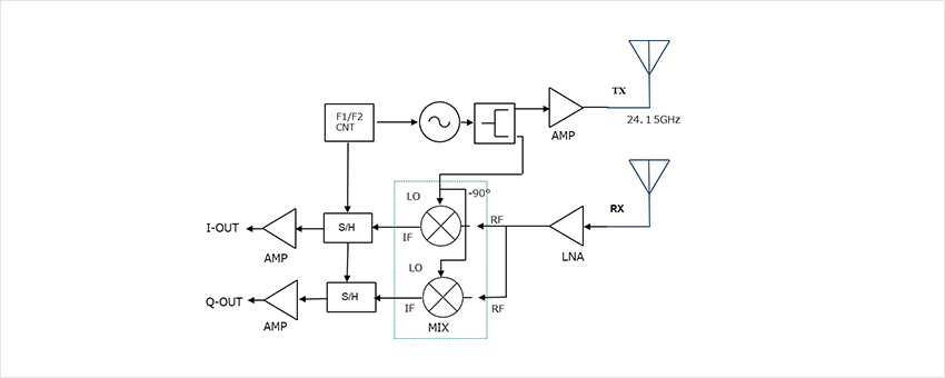
FSK Doppler Sensor Functional Block Diagram
VCO tuning voltage determines F1/F2 . (Some devices may use PLL control of these frequencies.)
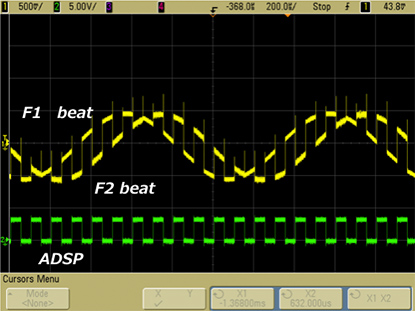
In order to separate the F1/F2 signals, sample & hold is applied to the mixer output. Using AD conversion, each signal is reproduced by rearranging the voltage values obtained with these timings. Phase difference is obtained from the result.
Phase 80deg fb 1kHzPhase 180deg fb 1kHz
FSK Doppler Sensor Features
It is possible to simultaneously measure the distance and velocity of the moving target.
It is possible to measure distance while switching between short-range and long-range applications through optimal selection of the two frequencies.
It is mainly used to measure the distance of a single object.