Featured products
1-Cell protection IC for Li-Ion / Li-Polymer batteries with Reset and Forced Standby function
September 17, 2021
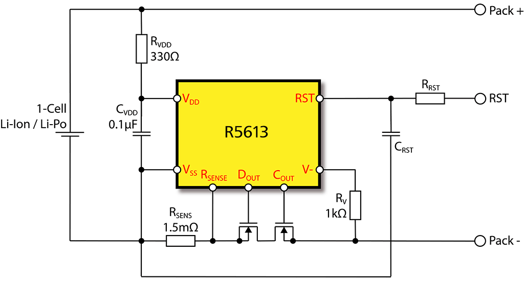
The R5613 is a primary battery protection IC for rechargeable 1-cell Lithium-Ion and Lithium Polymer batteries. It is designed to enforce strict usage limits keeping the battery cell in optimal condition and preventing critical overload conditions. Target applications are Li-Ion batteries or battery packs for portable devices such as smartphones, smartwatches, fitness trackers or other electronic gadgets.
Nisshinbo Micro Devices is a pioneer and has over 20 years of experience in developing battery protection ICs, the new R5613 features standard functions like over-charge and over-discharge voltage, discharge overcurrent and charge overcurrent and a short circuit protection. Several advanced functions were added which distinguishes the product from the conventional products. A new reset pin was introduced to enable controlling the IC externally, the pin has two optional functions which are selected by product version.
Reset version:
The RST input pin is by a P-channel open-drain output type and has an internal resistor to pull down to Vss. When the Reset function becomes active (RST pin = VRST > VRDET & tRST timer expires), the IC turns off the charge and discharge control MOSFETs to disconnect the battery from the charger. As a result, the charge current and discharge current are stopped. The Reset function is released by (RST pin = VRST < VRDET & tRREL timer expires). This function is used for checking leakage of the battery pack in the manufacturing factory.
Forced-standby version:
The RST input pin is by a CMOS output type and has an internal resistor to pull down to Vss. When the Forced-Standby function becomes active (RST pin = VRST > VREDT & tRST timer expires), the IC turns off the discharge control MOSFET and pulls the V- pin up to Vdd internally. As a result, the IC becomes Forced-standby more and current consumption is kept to minimum. The Forced-Standby function is released by connecting a charger. (V- < VRREL & tRREL timer expires)
Traditional current measurement by using the MOSFET on-resistance depends on several specific parameters making the overcurrent threshold less accurate and causes a large margin. A special two-step discharge overcurrent detector and the use of an external current sense resistor addresses this issue and makes this product ideal for applications that require enhanced safety features. The protection circuit is triggered by two critical discharge overcurrent thresholds, where the lower threshold has a moderate response speed and the upper threshold a fast response speed.
Additionally, the external current sense resistor value can be in the range of 1.5 mΩ which results in a lower heat dissipation at high currents.
The R5613 has a much lower current consumption (Typ. 2.0 - 2.5 µA) compared to predecessor products which is especially important for those applications with a small battery capacity.
The IC automatically enters the standby mode once the cell voltage drops below a certain threshold, some internal circuits will shut down, reducing current consumption and minimizing further discharge.
Optional functions are available per product version, such as the 0 V battery charging, which offers the option to allow / disallow the battery to recharge from a deep discharged state. Another option is to select between auto-release and latched release from overvoltage, undervoltage and discharge overcurrent status.
The R5613 is available in an 8 pins DFN1616-8B package, measuring L1.6 x W1.6 x H0.4 mm. Samples and evaluation boards are available from authorized local distribution channels and online partners.