Featured products
60 V Input / Synchronous Buck DC/DC Converter Controller
November 15, 2021
The R1260 is a buck DC/DC converter controller with a wide input voltage range up to 60 V and absolute maximum rating of 80 V. An adjustable output voltage range can be specified from 1.0 to 16 V and the output current is based on your requirements, depending on the selected external N-channel MOSFETs. The product offers maximum design flexibility since various settings can be tailored to the specifications of the application. An array of protection circuits are embedded to intervene in critical failure events and prevents further damage to other delicate electronic circuits. It is targeted for consumer, industrial and automotive applications and is added to our Product Longevity Program for long term availability.
When a system designer specifies a non-isolated DC/DC converter for a new circuit, considering the needed input voltage range is just as important as considering the required performance characteristics and features. This new product is a superior and flexible solution which meets these requirements with ease. Today’s popular power sources for automotive or industrial applications range from 12, 24 or 48 V or higher, the R1260 is able to handle up to 60 V input voltage and has an absolute maximum rating of 80 V. The adjustable output voltage can be set from 1 to 16 V. Additional high and low-side N-Channel MOSFETs are required complementary to the DC/DC Converter Controller.
-
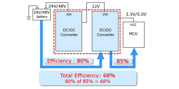
Conventional 2-Chip Solution
-
Improved results with 1-Chip Solution
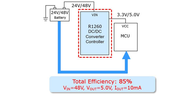
Conventional 2-chip solutions sourced from a wide primary input voltage to generate power to low voltage applications generally have a poor total efficiency. The R1260 provides improved results and is an excellent single chip solution with an efficiency of 85% according to the shown configuration.
-
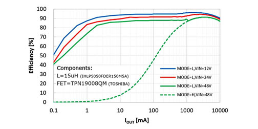
Efficiency Vout=5.0V , Fosc=250kHz
-
The R1260 has a unique current mode PWM architecture and proves to be a very stable DC/DC converter with 95% peak efficiency. Note that in automatic PWM/VFM switching mode the performance remains at a high level, even at a low 1 mA output current.
Three different operating modes are available, controlled by the mode pin:
- Automatic PWM/VFM mode, to maintain high efficiency under light and heavy load conditions, the device automatically switches between PWM and VFM mode.
- Forced PWM mode, the frequency is fixed under all load conditions, so it is easy to reduce noise.
- PLL_PWM mode, makes it possible to synchronize the frequency to an external clock, and by changing the switching frequency, the frequency band that affects the system performance can be avoided.
The phase characteristics can be adjusted by an external element to make optimisations for the operating conditions.
A variety of protection circuits are available, which contributes to the safe operation of the application. When the device is not ready and any of the protection circuits or states below are active, the Power-Good pin (PGOOD) will provide a fault signal to the system:
- CE pin disabled (when the chip is disabled)
- UVLO (undervoltage lock-out, input voltage below minimum value)
- Thermal Shutdown (junction temperature exceeds 160°C)
- During Soft Start Time (slow ramp up of the output voltage)
- UVD or OVD (under and overvoltage detection, output voltage deviates over ±10%)
- Hiccup- or Latch-type overcurrent protection
The designer has an option to select between a Hiccup-mode or Latch-mode overcurrent protection, depending on preference. Hiccup-mode overcurrent protection turns off the chip after detecting an overcurrent condition and tries to resume to normal operation after a delay time. The overcurrent state in Latch-mode does not automatically return to normal operation, but requires a restart of the chip after removing the overcurrent condition.
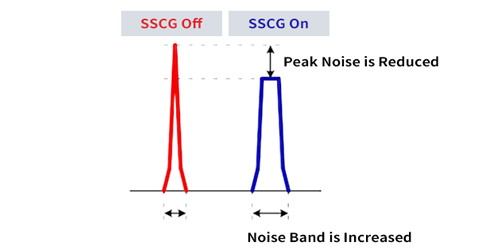
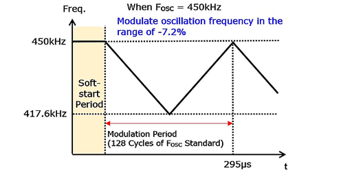
An EMI reduction can be achieved by using the optional Spread-Spectrum Clock Generator (SSCG) for a diffuse oscillation frequency at PWM operation. If the oscillator frequency of the DC/DC converter is modulated slightly via SSCG (-7.2% linearly and back to the original frequency during 128 clock cycles), the EMI energy is spread rather than concentrated at one frequency resulting in a lower EMI emission from the DC/DC converter.
DC/DC converter is modulated slightly via SSCG (-7.2% linearly and back to the original frequency during 128 clock cycles), the EMI energy is spread rather than concentrated at one frequency resulting in a lower EMI emission from the DC/DC converter.
The R1260 is available in an HSOP-18 package, evaluation boards are now available from approved local distributors and online partners. We distinguish three different versions for consumer, industrial and automotive purposes. (AEC-Q100 compliant soon).
R1526 has an array of safety features, protecting the voltage regulator and other parts of the application from possible damage and failure.