


What should be considered when using reset ICs?
Voltage Detectors (Reset ICs)How to use
When connecting a resistor (R1) to an input of this device, the input voltage decreases by [Device’s Consumption Current] x [Resistance Value] only.
And, the cross conduction current*1, which occurs when changing from the detecting state to the release state, is decreased the input voltage by [Cross Conduction Current] x [Resistance Value] only. And then, this device will enter the re-detecting state if the input voltage reduction is larger than the difference between the detector voltage and the released voltage.
When the input resistance value is large and the VDD is gone up at mildly in the vicinity of the released voltage, repeating the above operation may result in the occurrence of output.
As shown in Figure A/B, set R1 to become 100 kΩ or less as a guide, and connect CIN of 0.1 µF and more to between the input pin and GND. Besides, make evaluations including temperature properties under the actual usage condition, with using the evaluation board like this way. As result, make sure that the cross conduction current has no problem.
-
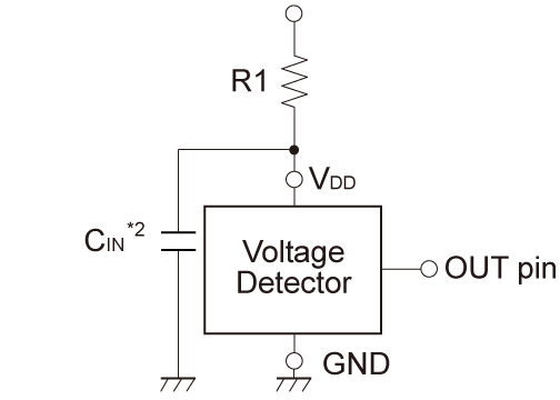
Figure A
-
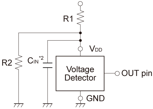
Figure B
- *1In the CMOS output type, a charging current for OUT pin is included.
- *2Note the bias dependence of capacitors.
Related Products
If you still have questions.
-
Search Other FAQs
-
Enter your question via our web form.