


[Example]
Trouble shooting-Additional Voltage Detector (Reset IC) solves the problem
Checking circuit itself seemed to be OK, but a trouble is detected! As is often the case with such a trouble, an additional component is used.
Here, the actual trouble shooting example is introduced. It might be useful to choose a device not only for trouble shooting but also just a simple component's selection.
Case 2:Additional Voltage Detector(Reset IC) solves the problem
Voltage Detector ICs are generally used as supervisory circuits for power supply for uCons. However, uCons usually have the supervisory function of their own. The role of the voltage detector ICs is not only such a supervisory circuit.
This example is such a case, an additional VD solves the problem.
Background of the trouble
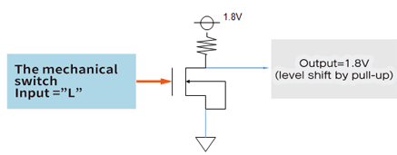
When an application wakes up by using a mechanical switch, an input node for the MOSFET driven by the mechanical switch should be "L" for a certain time. However, the voltage was unstable for a low percentage in mass production and found it to be 100% secured the level as "L".
The circuit design change opportunity is limited, and area size is also limited.
Customer's issue and condition confirmation
To solve the problem, some critical points must be considered.
| Check points | Customer's issue and condition confirmation (Check points) |
|---|---|
| When the mechanical switch is pushed, the input is pulled down, and when the switch is released, then the input is pulled up to 3V. | The role of the mechanical switch |
| The mechanical switch is connected to the gate of a MOSFET, the gate voltage should be stable "H" or "L" level. To turn on and off of the MOSFET, the "L" level should be close to 0V, and "H" level should be close to 1.8V. | The appropriate voltage to drive the connected MOSFET |
| For using a voltage detector to solve the problem, the input voltage is beyond the threshold from "L" to "H", the released delay time is necessary. | Delay time (for keeping "L" level before changin into "H") |
| The mount area size should be small as possible. | Mount Area Size |
Trouble shoooting Process
According to the information from the customer, part can be sorted out.
Components selection conditions
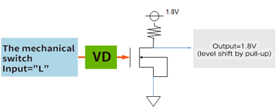
Adding a voltage detector between the mechanical switch and the gate of MOSFET
Supervisory voltage is the output voltage range of the mechanical switch. The voltage range is from 0V to 3V. Indefinite voltage range must be avoided, therefore a voltage detector with SENSE pin is suitable.
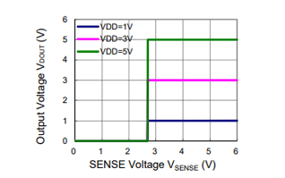
Typical Characteristic of a voltage detector with SENSE pin.
The power supply and sense voltage are separated, therefore, when the input voltage for SENSE pin is from "L" to "H", while the sense pin voltage is from 0V to released voltage level, the output voltage keeps "L" level. The figure shown right is the typical characteristic of the voltage detector, “ R3118”(2.7V threshold type).
Delay time setting
Adjustable delay time is suitable for the system. So, the released delay time should be adjustable by an external capacitor.
The device candidate is the R3118x.
Detector Threshold Voltage
Considering the distribution of the sense pin threshold, the detector threshold target is less than 2.5V and more than 2.0V.
Mount Area Size
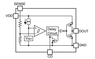
The block diagram of the R3118xxxxC (CMOS output type)
The mount area size should be very small, Option is tiny DFN(PL)1212-6 package.
To reduce the number of components, the output type is CMOS type.( pull-up resistance is not necessary.)
|
|
Trouble shooting
- Additional voltage detector IC solves the problem
- Additional voltage detector IC solves the problem
The voltage detector IC could be used in such a trouble shooting mentioned above.