


High Noise Immunity Power Management ICs to Combat Against Electromagnetic Noise
Annoyed by Failing Noise Immunity Testing after Finishing Board Design?
Have you ever experienced a malfunction due to low noise immunity after developing a new application board? This problem can sometimes happen after passing characteristics tests. Finding the cause of the problem can be very expensive and time consuming. If you are lucky, you could locate and identify the components with the problem and then search for suitable replacement parts. However, it is not always so easy or so simple. In the worst case, you may have to redesign the board which is very costly and time consuming. It is difficult to predict how noise will affect the developing application and adding countermeasures is one of the main factors that lead to increase development time and cost.
Without proper noise immunity, electromagnetic noise can cause abnormal function which may lead to injury or fatal accident especially as electronic devices are increasingly used in cars and industrial equipment. Therefore, it is critical that today's electronic systems take proper precautions to safeguard against unwanted noise.
Importance and Problems on Electromagnetic Susceptibility (EMS)
Everywhere we go, we are surrounded by invisible electromagnetic noise which increases at a high rate with the evolution of electronic devices. To ensure stable operation of electrical devices under an environment full of electromagnetic noise, there is a growing list of requirements for systems to be equipped with high noise immunity functions. Here are a few examples of common noise immunity requirements: ISO 11452 is an international set of immunity standards and guidelines for automotive electrical components, Transverse Electromagnetic (TEM) call method, and Bulk Current Injection (BCI) method. If a system cannot pass noise immunity testing, the time and cost would increase due to the need to re-design the circuit and rerouting the wiring patterns of the board.

Incident Cases
There are many cases where manufacturer’s product malfunctioned due to electromagnetic noise and were later required to take corrective action. These cases demonstrate the importance of EMS countermeasures to be as strong and robust as possible and to protect against electromagnetic interference from other devices.
Incident Cases Relating to Electric Wave Announced by Ministry of Internal Affairs and Communications
| Type of Affected Device | Affected | Type of Disorder | Interferer | Detail | Cause and Countermeasure |
|---|---|---|---|---|---|
| Communication facility | PC | Malfunction | Illegal CB radios | Computer Malfunction | Unspecified multiple illegal CB radios. |
| Home appliance | Automatic Door | Malfunction | Illegal CB radios | Automatic Door Malfunction | Countermeasures taken by product manufacturer. |
| Home appliance | Electronic bidet | Malfunction | Illegal CB radios | Electronic bidet malfunction, making the floor water-soaked. | Unspecified multiple Illegal CB radios. Countermeasures taken by product manufacturer. |
| Home appliance | Radio-controlled wrecker | Malfunction | Illegal CB radios | Malfunction | Unspecified multiple Illegal CB radios. Countermeasures taken by product manufacturer. |
| Sensors | Ultrasonic diagnostic equipment | Noise | Neon tube for indoor lighting | Marble noise generated during medical diagnostics, occurred frequently. | Sweep noise was found at frequency from 2 to 5MHz. Defective neon tube for indoor lighting caused the malfunction by oscillating abnormally. Replaced with a normal one. |
| Sensors | Electrocardiograph | Malfunction | Power induction | Irregular fluctuations in cardiograph | Abnormality inducted by the power supply. No failure found when powered by a battery. The equipment was replaced with another model. |
| Sensors | Business-use electronic thermometer | Malfunction | Unnecessary radio wave | Business-use electronic thermometer malfunction | Affected by unnecessary radios, etc. Countermeasures taken by product manufacturer. |
| Sensors | Ultrasonic diagnostic equipment | Malfunction | Unnecessary radio wave, power induction | Multiple noise generated during ultrasonic diagnostics at a hospital. Occurred during using a probe from 2.5 to 7.5 MHz. | Noise generated from multiple sources. One of them is not unnecessary radio waves but induction noise from an elevator to the power supply. |
Cited from Ministry of Internal Affairs and Communications in Japan
We have power management ICs which achieve high electromagnetic noise immunity. Nisshinbo Micro Devices ICs can provide stable supply voltage under very harsh environment where noise and various frequency are all around.
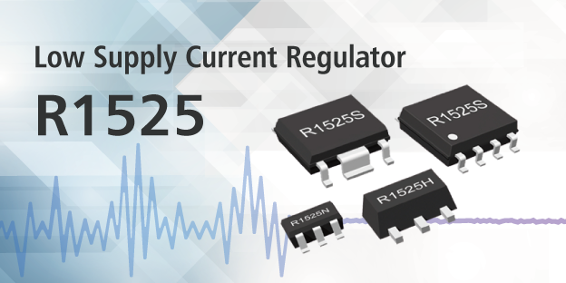
The R1525 series and R1526 series are voltage regulators and the R1540 series is a voltage tracker. All three families are high-noise immunity power management ICs developed using Nisshinbo Micro Devices’ proprietary circuit technology. They can supply a stable voltage even under a wide noise frequency condition of 150 kHz to 1 GHz.
The power supply of an off-board sensor system, for example, needs additional components for noise reduction, as electromagnetic noise generated by the wire harness may affect the sensor’s operation. Our "high-noise-immunity power management ICs" eliminate the need for additional components, which reduces mounting area because power management functions and noise suppression functions are all in one chip.
-
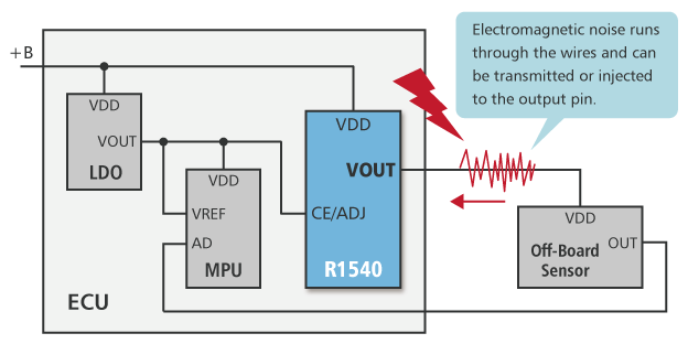
R1540 Circuit Example
Since electrical wires can transmit noise, ICs should have electromagnetic-noise-immunity.
-
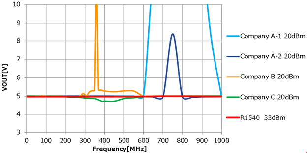
DPI Test Results
There is no visible output voltage fluctuation even after applying 33 dBm noise!
High Noise Immunity Power Management ICs
* Note: The operating temperature range varies for different products. For more details, please check each product page.